| You are here: Home » Import CAD Formats » IGES |

|
Okino's PolyTrans|CAD provides the defacto 3D IGES file import conversion solution used by the world's primary & professional engineering, aerospace, military, corporate, animation/multi-media and VR/AR industries. We were one of the original pioneers of IGES conversion software from the 1980's onwards and as such we understand IGES like the back of hands.
IGES is an excellent file format for data translation when such files are sourced properly (which will be explained further below).
Okino came to pioneer the MCAD conversion market over the last 30+ years and as such our IGES import solution has been designed to handle super-ultra-massive datasets that would otherwise choke and drag other conversion solutions to their knees. Okino software is well known, and sold specifically, for its ability to handle IGES files from the very smallest to the very largest in a rock solid and robust + efficient manner.
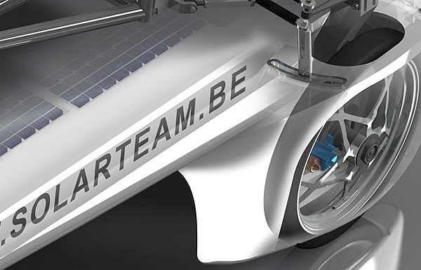
Technical illustration of solar powered vehicle.
Converted from CATIA-v5 via IGES and PolyTrans|CAD.
© Solarteam and Ludwig Desmet, Renderhouse BVBA.
The #1 Rule of Sourcing from IGES Data files
Always export as 'BREP Manifold Solids' (entity # 186)
and not as 'Free form surfaces' (entities # 128,143,144)
Okino literally exists to preach and teach all of our new and existing users how to properly source their IGES files.
It must be explained, and understood, that there are 3 completely different versions of IGES:
- The obsolete 1980's "Bounded Surfaces"
- The obsolete 1990's "Surfaced NURBS"
- The post-2000's "BREP Manifold Solids"
As the #1 epidemic of a problem in the conversion world today, it is very common for 3D graphics users to receive their IGES files as the long obsolete 1990's version of 'Surfaced NURBS'. Rather, you absolutely must source your IGES files as the modern "BREP Manifold Solids" variant. It will make a night and day difference in the quality, fidelity and robustness of your IGES file conversions.
If you source your files as the the old-school, 1990's 'Surfaced NURBS' variant of IGES then you will encounter the following common issues, due to the fact that such IGES files only have a loose 'soup' of NURBS geometric surfaces:
- Geometry objects exploded into thousands of single pieces
- 'Patch cracking' between adjacent faces
- Randomly oriented faces
- Randomly oriented geometric face normals
- Shading anomalies and black banding
- Overlapping geometry
The solution is rather simple and straightforward: when IGES files are to be used, ask your vendor to choose the export option for "BREP Manifold Solids", or use a STEP AP214 file. The 'BREP topology' information which is output to such modern variants of IGES will overcome all of the issues listed above.
How can you easily determine which of 3 variants of IGES data you have in hand? Read further down this page in this section.
Technical details about Okino's IGES importer can be read here.
Okino also recommends that you import your CAD files via these native importers (among others):
|
Autodesk Inventor
CATIA v5 Microstation ProE/Creo Rhino 3D Solid Edge SOLIDWORKS |

|
IGES is one of the original CAD vendor-neutral 3D data translation file formats which was designed for high fidelity data exchange between all major professional 3D modelling applications.
If you do not have access to the original native CAD files then either IGES 'BREP Solids' or 'STEP AP214' files would be the formats to request from your data vendor. You will want to ask for such IGES files to be exported as 'BREP solids' (and not 'Surfaced NURBS').
As an ANSI standard since 1980, IGES has been used in the automotive, aerospace, and shipbuilding industries. Version 5.3 (1996) is the last published and stable standard of IGES.
IGES files from the CAD and MCAD industry will typically contain these fundamental elements and structures:
- NURBS analytic/parametric geometry
- NURBS/bicubic curves & 3D polylines
- 'BREP' topology information (to define 'solids' geometry)
- CAD assembly hierarchy and structure
- Geometry instancing
- Part naming
- Meta data
- Unit-of-measure, geometric tolerance and other cursory source-modeller information
- And basic materials.
As noted in an opening section, there are 3 main variations of IGES: Bounded Surfaces, Surfaced NURBS and BREP Solids. You will only want to source and import from the latter, BREP Solids.
The following will explain how to open up an IGES file and quickly determine which of these 3 variations you have in hand.
IGES files are easily read ASCII text files that can be opened in any general text editor.
An IGES file is generally broken out into two distinct sections of which we are interested only in the first directory section. You will see a repeating pattern of two lines, each of which begins with a 3 digit number (such as 100, 102, 110, 124, 126, 314, etc).
Your Goal: scroll down through the file and scan for any of the following 3 digit numbers.
- If you encounter numbers such as 141, 142, 143 or 144 then you have an old-school variant.
- But if you encounter numbers which are 500-based or 180-based then you have a new-school (BREP Solids) variant. This is what you want to import.
This is an example of a 'BREP Solids' variant of IGES. Note the 500-based numbers in the first column and the 186.
502 31 1 1 0 0 0 001010000D 61 502 0 0 5 1 VERTEX 1D 62 504 36 1 1 0 0 0 000010001D 63 504 0 0 4 1 EDGE 1D 64 128 40 1 1 0 0 0 001010000D 65 128 0 0 6 0 SPLSRF 1D 66 508 47 1 1 0 0 0 001010000D 69 508 0 0 1 1 EDGELOOP 2D 70 510 48 1 1 0 0 0 000010000D 71 510 0 0 1 1 FACE 1D 72 514 215 1 1 0 0 0 000010000D 237 514 0 0 1 1 SHELL 2D 238 186 216 1 1 0 0 0 000000000D 239 186 0 0 1 0 MSBR 2D 240And this is an example of a 'Surfaced NURBS' variant of IGES. Note the 142, 144 and 128 numbers in the first column.
128 712 0 0 0 0 0 000010000D 145 128 0 0 10 0 0 0 FaceSrf 0D 146 142 1105 0 0 0 0 0 000010000D 217 142 0 0 1 0 0 0 FaceBnd 2D 218 144 1106 0 0 0 0 0 000000000D 219 144 0 1 1 0 0 0 Face 0D 220This is an example of a 'Bounded Surfaces' variant of IGES. Note the 141, 143 and 128 numbers in the first column.
141 316 0 0 0 0 0 000010000D 53 141 0 0 1 0 0 0 FaceBnd 2D 54 143 432 0 0 0 0 0 000000000D 77 143 0 1 1 0 0 0 Face 0D 78 128 433 0 0 0 0 0 000010000D 79 128 0 0 23 0 0 0 FaceSrf 0D 80
The very first question that we ask of our new customers is 'From which MCAD program is your IGES file coming from?'. That can be very important information, depending on the name of the source MCAD program. For example, we would always want our ProE/Creo users to source via native (asm/prt) files or STEP AP214 whereas with SolidWorks we would prefer them to source either as native (sldprt, sldasm) files or as properly exported 'IGES BREP solids' files.
IGES files are easily read ASCII text files that can be opened in any general text editor. After opening the file in such a text editor you will want to look over the first few convoluted lines of the file. The name of the originating MCAD program will usually be defined within that sub-section. The following are some typical examples:
An IGES file created in Autodesk's Inventor software:
,,5HVILLA,27HNo Iges File Name specified, 23HAUTODESK INVENTOR R12.0,37HAG 1 utoDesk Inventor Iges Exporter R12.0,32, 38,6,99,15,5HVILLA, 1.0D0,2,2HMM,G 2 1,.08D0,15H20080711.205828, .01D0,10000.0D0, 19HNo Author specified, 25HNo G 3 Organization specified, 11,0,,33HNo Application Protocol specified; G 4An IGES file created in PTC's ProEngineer/Creo software:
PTC IGES file: testfile2_asm.igs S 1 1H,,1H;,13Htestfile2_asm, 17Htestfile2_asm.igs, G 1 49HPRO/ENGINEER BY Parametric Technology Corporation, 7H2007230,32,38,7, G 2 38,15,13Htestfile2_asm, 1.,2,2HMM,32768,0.5, 15H20090327.161152, G 3 0.0225861, 225.87, 8HSECHINYI,7HUnknown,10,0, 15H20090327.161152; G 4An IGES file created in SIEMENS UG NX Inventor software:
1H,,1H;,53HC:\Users\abcdefgh\AppData\ Local\Temp\tempfilename.prt, 87HC:\UG 1 sers\abcdefgh\Desktop\Mudline\this is the long filename of the assembly.G 2 6_iassy.igs,7HNX V7.5, 27HSIEMENS PLM SOFTWARE NX 7.5,32,38, 16,38,16, 53HCG 3 :\Users\abcdefgh\AppData\Local\Temp\ tempfilename.prt,1.0,2, 2HMM,3,0.0, G 4 15H20111101.094252, 1.0E-005,10000.0,,,11,0, 15H20111101.094200; G 5And an IGES file created in SOLIDWORKS software:
1H,,1H;, 18Htempfilenam.SLDASM, 62HC:\Users\abcdef\ Documents\Projects\012-G 1 0124-04\tempfilenam.IGS, 15HSOLIDWORKS 2022, 15HSOLIDWORKS 2022,32,308, G 2 15,308,15,18 Htempfilenam.SLDASM,1.,1,2HIN, 50,0.125, 13H130903.085111, G 3 1E-008, 19684.6456692913, 6Habcdef,,11,0, 13H130903.085111; G 4
Okino's PolyTrans|CAD imports, optimizes and intelligently converts IGES files into all major 3D file formats, animation packages, military VisSim, virtual reality (VR) and augmented reality (AR) systems (such as Unity and Unreal Engine), and third party/OEM integrations.
IGES part and assembly files can be effortlessly and directly converted into such popular & common destinations such as:
- IGES (.iges, .igs) to AutoCAD (.dwg, .dxf)
- IGES (.iges, .igs) to 3ds Max (.max)
- IGES (.iges, .igs) to CADMATIC (.3dp)
- IGES (.iges, .igs) to CINEMA 4D (.c4d)
- IGES (.iges, .igs) to COLLADA (.dae)
- IGES (.iges, .igs) to DWF-3D (.dwf)
- IGES (.iges, .igs) to FBX (for Unity, Unreal and MODO)
- IGES (.iges, .igs) to JT Open (.jt)
- IGES (.iges, .igs) to LightWave (.lws, .lwo)
- IGES (.iges, .igs) to Maya (.mb)
- IGES (.iges, .igs) to Microstation DGN (.dgn)
- IGES (.iges, .igs) to OpenFlight (.flt)
- IGES (.iges, .igs) to NGRAIN 3KO (.3KO)
- IGES (.iges, .igs) to Rhino-3D (.3dm)
- IGES (.iges, .igs) to SketchUp (.skp)
- IGES (.iges, .igs) to STL (.stl)
- IGES (.iges, .igs) to Visual Components
- IGES (.iges, .igs) to Acrobat-3D (PDF via U3D) (.u3d)
- IGES (.iges, .igs) to VRML2 & X3D (.wrl, .x3d)
- IGES (.iges, .igs) to Wavefront (.obj)
- IGES (.iges, .igs) to dozens more 3D file formats

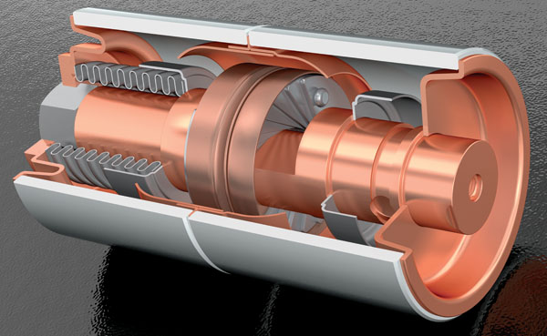
'Vacuum Interrupter' converted via IGES from 'One Space Designer' by Pieter Suur.


