| You are here: Home » Specialized Sections » How To: CAD to STL Conversions |
|
- Overview
- Features and Benefits to SketchUp Users
- How to Install & Utilize the SketchUp Conversion System
- 'Best Practices' for Proper SketchUp File Conversions
- Notes: Conversion of SketchUp Mesh Data to MCAD Solids Modellers
- Dialog Box Options - Enables Panel # 1
- Dialog Box Options - Enables Panel # 2
- Features and Benefits to SketchUp Users
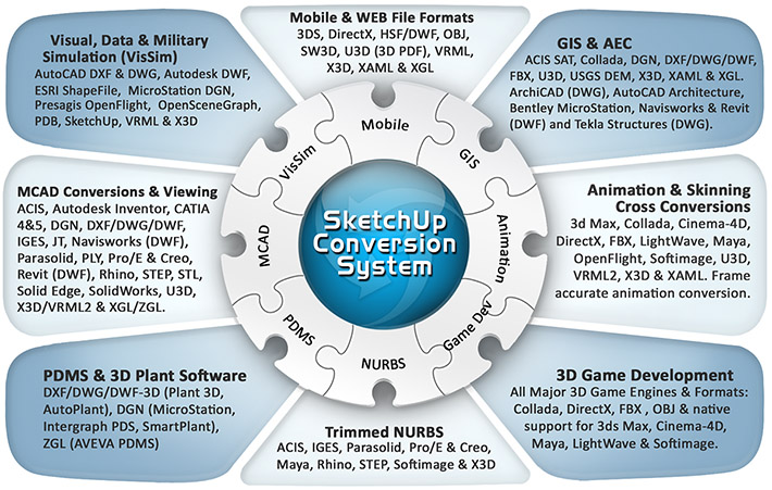
Okino's professional SketchUp conversion system intelligently and robustly creates native SketchUp files from almost every 3D CAD, DCC, animation and VisSim program, such as: 3ds Max (via PolyTrans-for-3dsMax), Maya (via PolyTrans-for-Maya), Autodesk Inventor, CINEMA 4D, CATIA v4, CATIA v5, Collada, DirectX, DGN, DXF/DWG, DWF-3D (AutoCAD, Navisworks and Revit), Electric Image FACT, ESRI, FBX, HOOPS 3D, IGES, JT, Lightwave, OpenFlight, PARASOLID (such as for Siemens UG NX), PDB (protein database), PLY, ProE/Creo (using real PTC Creo, not reverse engineered software), Rhino, Softimage (XSI), Solid Edge, SolidWorks, STEP, U3D (from PDF), VRML1+2+X3D, Wavefront OBJ and others (if you don't see your required format then just email us and we'll explain the standard conversion route for that program or file format).Okino's conversion system is and has been the key reference-implementation tool for repurposing all major CAD/MCAD, DCC and VisSim content into quality SketchUp models. If you have 3D models which you can't get converted to SketchUp format properly then we can help you easily do it -- the default conversion options will always perform a proper conversion (although, at most, you may need to change the relative export scaling, as SketchUp is senstive to model size).
Click for larger image.
Note: some conversion paths shown in this image are uni-directional only.Please also refer to the corresponding SketchUp import converter.
The SketchUp import/export conversion system is provided as part of the base-level PolyTrans and NuGraf programs.
If you are new to Okino and our software then please take a moment to read this page about what has made our software's usage so wide spread throughout the 3D industry. Okino's core and founding philosophy has been "one to one" personal customer relations and support, an often overlooked and neglected aspect of today's software industry. Our software is used throughout the world by tens of thousands of 3D professionals in mission & production critical environments, backed by respectable personal support directly from our core development team.
If you wish to export to Collada, or Google Earth, then please also refer to Okino's extensive Collada implementation (which includes refined and special support for Google Earth).
SketchUp is a popular 3D design product originally developed by @Last Software (http://www.sketchup.com) and now owned by Trimble, Inc. Okino recognized the growing popularity of SketchUp (well before it was purchased by Google and then Trimble) and as such we worked directly with the original SketchUp developer to create the very first set of independent, professional and fully compliant SketchUp 3D converters outside of the SketchUp program itself. Okino's SketchUp conversion system is used throughout the 3D production world by everyone from Disney to LucasFilm to Sony Productions to NASA and many people just like yourself.
SketchUp has particularly stringent requirements on the 3D data that it can import and hence this Okino exporter 'goes the extra mile' to clean up, optimize and manipulate the exported data so that it will show up properly within the SketchUp program. These manipulation options are exposed through the two exporter panels.
- The most robust, efficient and highest quality 3D production-proven converters for
SketchUp. The modules have been heavily utilized by our high-end 3D professionals and
production studios, and hence are well refined and robust at this point in time.
- Resulting translated files are 'Render Ready' meaning that they can be loaded and
manipulated in the SketchUp program with little or no changes necessary.
- Conversions are provided to all standard and common 3D file formats as noted
in the list above and as listed here. Additional
file formats and native integrations are provided by
third party products.
- One of the key uses of the SketchUp conversion system is with our dedicated
PolyTrans-for-3dsMax and
PolyTrans-for-Maya native conversion
systems for 3ds Max and Maya. The native conversions will allow models, such as
office buildings, with large amounts of instancing (such as windows), texturing, hierarchy
and polygonal count to be efficiently converted bidirectionally. Controllable via a MEL-script interface (Maya) or MaxScript (for 3ds Max) for both
importing and exporting of SketchUp files.
- The only dedicated and bi-directional conversion system between native SketchUp files and
native CINEMA-4D files, using PolyTrans-for-CINEMA-4D.
- Over the last 2.5 decades Okino has pioneered the concept of bringing complex
CAD assemblies into SketchUp. These are very refined
and efficient CAD pipelines. A typical complex CAD conversion process only takes
a few minutes or less, including full scene optimizations. There is no concept of
spending days or weeks 'trying' or 'struggling' to get CAD data into these programs,
a myth wrongly and purposely propagated by others.
- Strong and robust CAD file support: Autodesk Inventor, CATIA v4, CATIA v5, DXF/DWG, DWF-3D (for AutoCAD, Revit, Navisworks and Inventor support), IGES solids, JT, Parasolid, native ProE/Creo (which uses an embedded copy of PTC Creo for perfect translations), Rhino, Solid Edge, SolidWorks, STEP, STL, U3D, VRML & X3D.
- The hidden magic in the conversion process is Okino's unique and proprietary CAD optimization processor, integrated into each of our CAD importers. This processor is by far the most complex aspect of our entire 3D CAD conversion software pipeline. Turn it on and it'll wrangle large and unwieldy CAD assemblies into refined datasets for efficient animation, rendering or interactive viewing.
- Most importantly, Okino does not use reverse engineered CAD modules as is done by others, but rather licenses, utilizes and/or accesses the industry standard CAD geometry engines from Autodesk (Inventor), Dassault Systemes (CATIA), PTC (ProE/Creo), Solid Edge, SolidWorks, Siemens (JT Open toolkit) and others.
- Import parts, assemblies, hierarchy and materials directly from a running copy or native file of Autodesk Inventor, Solid Edge or SolidWorks into any Autodesk product. Unique!
- Strong and robust CAD file support: Autodesk Inventor, CATIA v4, CATIA v5, DXF/DWG, DWF-3D (for AutoCAD, Revit, Navisworks and Inventor support), IGES solids, JT, Parasolid, native ProE/Creo (which uses an embedded copy of PTC Creo for perfect translations), Rhino, Solid Edge, SolidWorks, STEP, STL, U3D, VRML & X3D.
- Strong ties to the visual simulation (VisSim) community with proven OpenFlight,
VRML 1.0 +2.0 and X3D support.
- Automatic conversion of foreign 2d bitmap image file formats. During export, these
file formats are converted on the fly and embedded directly into SketchUp files. During
import from SketchUp files, the images are extracted and converted to disk-based TIFF files.
- Access to robust polygon processing tools which can take impossible-to-render
datasets and turn them into renderable models (auto-weld, auto-unification,
reorientation of normals, polygon reduction).
- Okino provides free, quick and highly educated support for its software direct from the main management team and senior developers, and not from online forums or untrained front-line tech support people. Unlike faceless companies where support may be non-existent, we personally know tens of thousands of our customers by first name, email address and company background.
- First and foremost, before you do anything, send an email to Robert Lansdale,
Okino's CTO, with an quick explanation of what source programs you wish to import from (especially if
they are CAD programs). This technical chat is something which is done with every new or
existing Okino software user as a fundamental aspect of how we personally support our software, but particularly with
new users. 80% of our new customers bring with them incorrect notions about which file format, file
format version or conversion method should be used when importing 3D data files (notably if they are
receiving IGES or Parasolid CAD files from a remote vendor).
- Download and install the stand-alone Okino PolyTrans or NuGraf combined demo.
- Optionally run the "Super Installer" for 3ds Max or Maya integration.
- Execute the stand-alone PolyTrans or NuGraf program, PolyTrans-for-3dsMax within
3ds Max or PolyTrans-for-Maya within Maya.
CINEMA-4D conversions are always to be done inside
of the Okino stand-alone software and never within CINEMA-4D itself.
- Import from your source file format using all default options. Ideally, you will have exchanged
one or two emails with Robert Lansdale by this point so that he can explain the proper + best method
to source your 3D files.
- Take a look at the imported model's extents by mousing over the model and examining the XYZ
values on the status bar, or by using the "Measure Distance" toolbar button to measure the width of the
model. You will want the model to be roughly 1x1x1 to 1000 units
in size, as SketchUp will otherwise display your model badly if it is too large or too small.
If too small, re-import with the scale factor set to 10 or 100 on the last panel of the CAD importer.
If too large, re-import with a smaller scaling factor such as 0.1 or 0.01.
Continue this process until you can have the model imported at a sane "size" (usually you can import
all models in one pass, once you get to know of the best 'scale' factor to use).
This will give you ideal z-depth buffering in SketchUp as otherwise the model may end up looking like
'swiss cheese'.
- You may want to review the "'Best Practices' for Proper SketchUp File Conversions"
section to become familiar with some of the oddities involved with the SketchUp software.
- Execute the Okino SketchUp exporter and use all default options except that you should enable the
two checkboxes titled "Hidden" on the first exporter panel.
- Load the final .skp file into SketchUp.
Many people use the SketchUp program but few people are aware of its technical limitations and oddities. Okino was the first company to write a professional conversion system for SketchUp, along with the original developer of the SketchUp program, so we have been well aware of these oddities from the very start in 2005.
SketchUp was originally designed as a very simple & easy to use "sketching program", whereby models were made from a series of equi-sized polygons to create architectural scenes. It was never designed to import and handle CAD models, nor was it ever envisioned that one day SketchUp would become popular such that it would be used to import generic models of all varieties and topologies.
The basic technical limitations and problems with the SketchUp software are:
1. SketchUp has no ability to import any vertex normals from another file format. This is a problematic shortcoming. Vertex normals define the smoothness of an object and as such they are critically needed when importing from CAD files. SketchUp uses "edge lists" and "edge smoothing flags" to decide whether two adjacent polygons should appear smoothed in the SketchUp user interface. While this concept was ideal for simple, hand-sketched architectural models, it can often fail when handling CAD models which contain a mixture of abrupt and smooth edges all in the same model. Thus, special care must be taken when trying to import CAD files into SketchUp so that "black banding" shading artifacts and rogue edges do not show up. There is no "one size fits all" solution to overcome this lack of vertex normals in SketchUp.
2. The Merge coplanar polygons internal function of SketchUp is broken. Enabling this exporter option will often cause holes to appear in a CAD model and it is known to crash on occasion. Hence, don't enable this option on the SketchUp exporter. This is a bug of the SketchUp software itself and not of the Okino exporter.
3. SketchUp is known to delete tiny triangles from an imported dataset. This was told to us as being a design decision in 2005 by its original SketchUp developer. While that may be a good idea when sketching large-polygon architectural models, it is a potential problem when importing CAD files that are most often made up of tiny triangles. To overcome this problem, set the "Raw geometry scaling factor" parameter on the Okino SketchUp exporter to 10, 100 or 1000. This makes the overall model that much larger and hence the small polygons will not be deleted. In general, you should not see this problem in day to day conversions.
4. Exporting to a SketchUp file may slow to a crawl if the number of objects in a scene is above 2300, or thereabouts. This is due to the SketchUp SDK which becomes slower as the number of "grouping nodes" are created. This is out of control of Okino software development. Normally this is not seen because each Okino CAD importer has the "Optimize hierarchy" checkbox enabled, which will ensure that a source CAD file with a lot of objects is heavily reduced in terms of the overall object count. You can also disable the "Use SketchUp geometry instancing to reduce file size" checkbox on the SketchUp exporter, as it will always create a SketchUp "group node" that will add to the overall slowness of the SketchUp SDK's "create group node" routine. To put this into perspective, Okino software is made to push through millions of objects and grouping nodes, and many programs like LightWave, 3dsMax and Maya are capable of handling many 10's of thousands of nodes before they start to become slower.
"Need to Know" Information
1. If an export process slows down to a crawl then you are trying to export too many nodes, and/or grouping nodes, to a SketchUp file. This is not an issue with any other program or file format.
Suggestions:
- Keep the "Hierarchy Optimize" checkbox enabled on each Okino CAD importer. That is a special feature of Okino software which heavily reduces the node count in a scene.
- You can run additional executions of Okino's hierarchy optimizer, prior to the SketchUp export process, by running the "Optimize Number of Objects & Folders" command from the "Win" menu of the upper-right "Selector Window" in the stand-alone Okino software. You can then determine how many instances (objects) remain in the scene via the "Scene Statistics" dialog box accessible from the "Translate!" or "File" menu of the stand-alone Okino software. In general terms, it is best if you can keep this node count down to well below 2000, or thereabouts, for faster SketchUp export.
- Disable instancing on the SketchUp exporter so that fewer grouping nodes are created in the SketchUp exporter SDK.
2. If a scene in SketchUp appears to have missing polygons, or has some odd shading problems on a subset of polygons, then this is most likely related to scene scaling issues. SketchUp's OpenGL shaded display can be finicky when it comes to the overall size (scale) of the geometry. Re-export the scene with the "Raw geometry scaling factor" option set to 10 or 100 (make the scene larger), or inversely to 0.1 or 0.01 (make the scene smaller).
Best Practices for CAD Conversions
We often have to assume that few people understand why the conversion of CAD files into SkechUp can lead to oddities, while such conversions to other file formats and programs do not. It all comes down to two concepts: "Geometry topology" and "Lack of vertex normals" in SketchUp. In CAD, a model can have a mixture of different topology, such as a portion of an object with a large number of tiny triangles located beside another portion of the same object with large-area polygons - SketchUp does not like such mixed topology and hence this can lead to "fans of black banding" or another shading anomalies. The use of "edge lists" instead of explicit vertex normals is the real culprit for all CAD conversion issues within SketchUp.
1 - Make sure the CAD Model was Created as "BREP Solids". Choose the Correct CAD File Format & Version.
Many people ask for CAD files from their vendors without an understanding of "what to ask for" or "how the source CAD files were structured". This can ultimately lead to bad shading anomalies in SketchUp, or in any old animation program which still uses "shading groups".
In very simple terms, you will want to ask your CAD vendor to:
1. Do their modeling entirely in "solids" and not as loose, independent NURBS surfaces. "Solids" are basically 2 or more NURBS surfaces that have added information attached to them ("BREP topology") that allows Okino software to make the imported CAD data "water tight" and so that all edges are shared (which is very important for artifact-free rendering by SketchUp). Section (4) further below exemplifies what happens if a CAD model is not created properly such that all of its NURBS surfaces share common edges and similar topology.
2. Export in a CAD format as "BREP Manifold Solids" and not the 1995-era "Surfaced NURBS". The latter will not be able to convey the all-important "BREP topology" information which is needed to ensure that all edges remain shared once converted over to SketchUp.
If the CAD model was created purely as "solids", with all NURBS surfaces sharing edges, then there should be little or no problems with having SketchUp import and display such models. Statistically, 99% of the CAD models we have converted to SketchUp at Okino work out fine. This is achieved by using the defaulted "Topology = Bodies" checkbox found on many of Okino's CAD importers (such as ProE/Creo, IGES, STEP, Parasolid and SAT).
2 - Set the Correct Scale on the Okino CAD Importer
Make sure your imported CAD model, within Okino software, is at least 1x1x1 units wide and not much larger than 1000 units wide. Many people blindly import CAD models such that they are just 0.01 units wide and then wonder why a destination program's OpenGL real-time display causes the surfaces to flutter or render incorrectly. You need to import your CAD models at a reasonable and sane size.
After import you can move the cursor around the 4 view windows in Okino software to get a sense of the size of the model (by watching the XYZ value change on the status bar), or by using the "Measure Distance" toolbar button to measure the width of the model. If the model is too small then re-import it with a larger scaling factor on the last panel of an Okino CAD importer (such as 10, 100 or 1000). If the model is too large then re-import it with a smaller scaling factor on the last panel of an Okino CAD importer (such as 0.1 or 0.01). Continue this process until you can have the model imported at a sane "size". A model which is just too small will not display properly in SketchUp (polygons will appear to be missing, which is a failing of the SketchUp software).
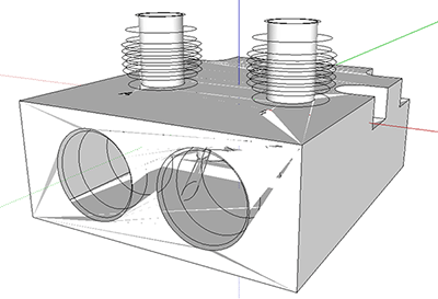
The following images exemplify this problem of SketchUp. The first screen snapshot (from the SketchUp user interface) shows an IGES file converted to SketchUp where the model was imported with no proper scaling, thus being only 0.00153 units wide. Many polygons "appear" to be missing.
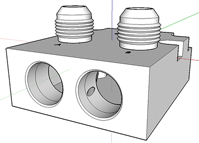
In the second screen snapshot, the IGES model has been imported using a scaling factor of 1000.0 such that it is now 1.53 raw units in width (an ideal size to display the model accurately within the OpenGL realtime display of the SketchUp software):
And here is another clear example of the scaling issues with the SketchUp OpenGL display functionality. The following image is of an SGI logo imported from SolidWorks, exported to SketchUp .skp format and loaded into the SketchUp user interface. All default options were chosen on the Okino SolidWorks importer and SketchUp exporter. This would be termed a "blind" conversion for which no proper choice of scaling or units matching was made.
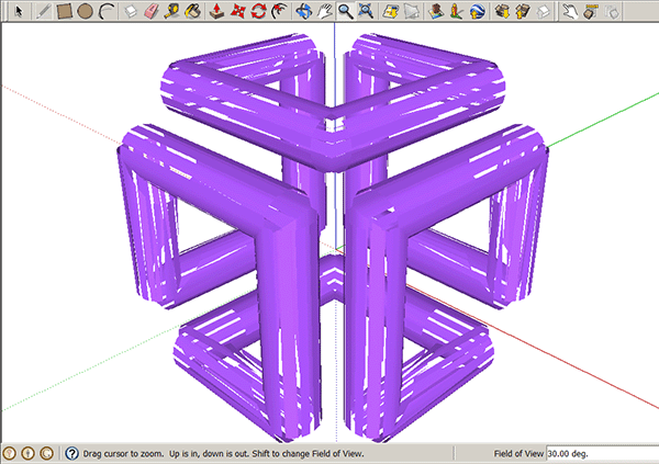
The problem, of course, is that the CAD model is too small for SketchUp to display properly. If you want to get a sense of the "size" of a model then look at it first in Okino's stand-alone software. In the following image the 3D grid of the "camera view" within Okino software clearly shows that the model is too small (only 0.06 units wide).
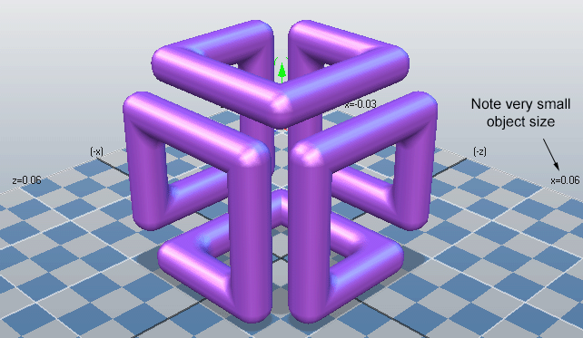
Since SketchUp purely and only uses "inches" as its primary, internal unit, the SGI logo conversion was redone with the "Unit Matching" combo box on the SolidWorks importer (on the last panel) set to inches. No scaling was set on the Okino SketchUp exporter. As shown, the SGI logo now displays properly within the SketchUp user interface since its size is now in the "sweet spot".
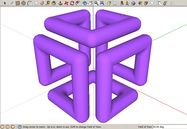
3 - Enable the "Hidden" Checkbox Options
A CAD model often looks better when its edges are hidden within the SketchUp user interface. This can easily be done by enabling both "Hidden" checkbox options on the Okino SketchUp exporter.
4 - For Rare Topological Cases -- Import from the CAD file as "Faces" and not "Bodies"
Let's look at a rare case to exemplify how the CAD -> SketchUp process can fail, due to known problems and limitations with the SketchUp software:
The following screen snapshot is of a CAD file which was created with different geometry topology. Each area delineated by royal blue lines is one NURBS surface. The handle is composed of several NURBS surfaces. The turquoise triangles represent the final polygon mesh that will be exported to SketchUp. Notice the big problem - the triangle edges and vertices are not shared between NURBS surfaces (across the royal blue edges).
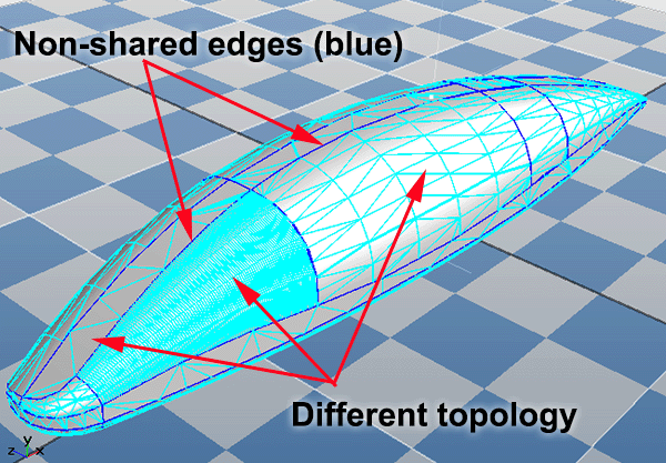
Due to the fact that not all the polygons share their edges, SketchUp will have trouble displaying this model, as shown in the following screen snapshot from the SketchUp user interface:
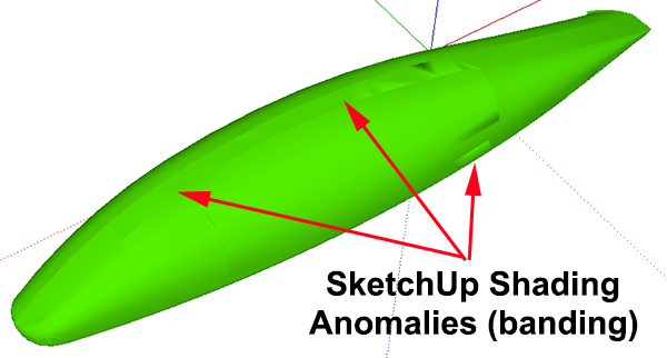
The current developers of SketchUp (Trimble) have acknowledged this as a problematic bug in the SketchUp software. This same model could be exported to almost any other 3D program without such shading anomalies showing up.
How can these shading anomalies be fixed or reduced?
- Ideally, the source CAD model should use uniform and similar topology across the object (part file) so that the final polygon mesh within SketchUp is itself uniform in size and layout.
- Ideally, the source CAD model should be created as "BREP Manifold Solids" and exported as "solids" to the CAD file format.
- The shading anomalies partly occur within SketchUp because a single mesh object contains multiple polygons which don't all have shared edges. A non-obvious, but technically okay "solution", is to import the CAD model with Okino's CAD importer set to "Topology = Faces" and with the "Hierarchy Optimize" checkbox disabled. In terms of the "bad" model shown above, what this does is to keep each NURBS surface (delineated by the royal blue lines) in its own unique SketchUp object, rather than all the NURBS surfaces being compressed into a single SketchUp object. The black banding will most likely disappear, but the downside is that there will be lack of shared smoothing between each (new) separate object. Until Trimble finally fixes these problems with SketchUp there will no mathematically perfect solution for these rare and odd cases.
5 - Run Okino's "Vertex Normals Welder" To Remove Rogue Edges in SketchUp
For the record we'll mention this rare case...
As mentioned previously, SketchUp makes two adjacent polygons "smooth" when both share the same edge. For Okino's SketchUp exporter, to make an edge "shared", both adjoining polygons must (1) share the same two vertices and (2) share the same vertex normals at the two vertices.
Sometimes a source model has shared vertices (which is good) but does not always have the 100% identical vertex normals on each side of a polygon edge (which is not good). This can show up in the SketchUp user interface as rogue edges, whereby single "random" lines can appear across a model. These lines indicate that the edges between two polygons are not shared (not smoothed), either due to unshared vertices or unshared normals.
To "tighten up" a source mesh model, so that is has shared vertices and shared normals, run Okino's "Process Polygons" menu command on the entire scene (using Okino's stand-alone software). Disable all options except "Combine Vertices" and "Combine Duplicated Vertex Normals". From an experience we had with an odd CAD model, we once had to change the type-in value from 0.001 to 0.01 for the vertex normals tolerance value so that more "random edges" were removed from the final SketchUp scene.
!! Important Notice to SketchUp -> CAD People !!
As a question we get 3 or more times per day, for the last 15+ years, no program can "convert" (with the press of a button) from a free-form, generic, SketchUp mesh polygonal model into any CAD NURBS-based file format such as IGES, STEP, Parasolid, ACIS SAT, ProE/Creo, Unigraphics NX, CATIA, etc. such that the final file can be edited as a trimmed NURBS or BREP solids scene. This has always been the the most misunderstood concept in the 3D graphics world, most notably on forums where this question is often posed and answered based on common misconceptions. Even with the following information, there are always those on SketchUp forums who still believe this process can be done (you can do it for CAD-like programs like AutoCAD or Rhino but not MCAD solids-modellers like SolidWorks, ProE, etc).
The lack of understanding is due to the basic fact that many people do not know the difference between polygon meshes and NURBS surfaces. MCAD "solids" modellers (such as SolidWorks and ProE/Creo) can only deal with NURBS surfaces as their primary editable geometry primitive - NURBS are like a plyable sheet of rubber that is trimmed and warped to fit over an entire car door, as a good example - on the flip side, mesh models define the car door as hundred or thousands of quad or triangle polygons. A soup of polygons cannot be converted back, at the press of a button, to an intelligent NURBS model just like water cannot be easily turned back into an ice sculpture.
As many of the 10's of millions of new SketchUp users have had no prior hands-on experience in CAD modelling, we always take time to teach and explain the basic concepts to them in our personal emails. Mesh to NURBS reconstruction has always been an unsolved aspect of the 3D graphics industry, as it ideally requires human intelligence to lay down the character curves and define the contours needed for good NURBS reconstruction. In the end, even with the best reconstruction software we outline below, you still need to become involved with the mesh to NURBS (or mesh to SubDivs to NURBS) reconstruction process in order to get a proper and "intelligently segmented" model.
Please note that there are a few CAD modelling programs which can import polygonal mesh data, albeit in as a non-editable "proxy graphic" in many cases. For example, Solid Edge imports mesh data when in the 'Ordered Environment', Inventor & ProE reads in mesh data as a proxy graphic, AutoCAD can import raw mesh data (as it was always more of a mesh-based modeller from day one), Rhino can import mesh data for mesh-tool editing, etc.
Most people we encounter want to "convert" from mesh-based programs (SketchUp, 3ds Max, CINEMA-4D) into SolidWorks. This by itself has caused tremendous confusion over the years as some people try to achieve this conversion via a VRML or STL import into SolidWorks. SolidWorks uses a known software developer "hack" to turn each mesh triangle into one "bilinear NURBS surface". This process is NOT converting the original mesh model into a high-order, smooth NURBS surface, as many people believe on forums or on posted YouTube videos. Such a conversion will bring SolidWorks to its knees for models with just a few hundreds triangles, as each triangle will be converted into its own, unique bi-linear (ie. non-smooth) NURBS surface. Some very low cost utility programs also promote such "mesh to solids" but in fact they are actually just pulling the wool over the eyes of unsuspecting people. Hence, "buyer beware" and please research your requirements before purchasing any such software.
For reference, the process of turning a mesh model back into a NURBS model (for re-export to a CAD program or file format) is properly done through the use of a "surface reconstruction" program. These programs provide interactive tools to aid a human end-user in re-surfacing a mesh model with high order trimmed NURBS surfaces. Some of the well known packages are: Geomagic Design, Geometry Systems - GSI Studio and headus, CySlice v3. Okino has no affiliation with any of these companies whatsoever. This list is from openly available information.
In the end, due to these high prices, most people just rebuild their mesh models in a popular MCAD modeller like SolidWorks as it costs less than a mesh reconstruction program (the pro version of SolidWorks also includes an interactive mesh reconstuction module).
Note: most 3D printers can accept VRML2 and STL formats, which are not "CAD formats" as some people believe. CNC milling machines, on the other hand, require the tangential information from a true NURBS surface and hence many of them will only accept a proper NURBS-based file format such as IGES or STEP.
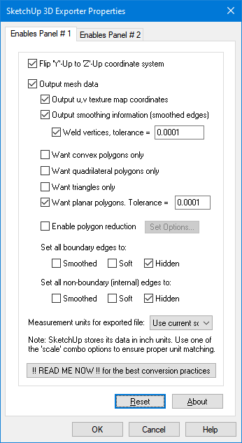
Flip 'Y'-Up to 'Z'-Up coordinate system
This option allows the default coordinate system to be set for the SketchUp file. It defines what will be considered the "Up" axis in the exported SketchUp file. Okino software uses a "Y" up coordinate system. Enabling this option will flip the source Y-up data of the internal Okino scene graph to a Z-up coordinate system of the exported SketchUp file.Output mesh data
If this checkbox is checkmarked then mesh geometry will be exported.Output u,v texture map coordinates
If this checkbox is checkmarked then (u,v) vertex texture coordinates will be exported along with the mesh geometry.Output smoothing information (smoothed edges)
If this checkbox is checkmarked then the vertex normals of the source 3D scene graph meshes will be approximated into SketchUp mesh edge smoothing information. In SketchUp, two adjacent polygons will appear smooth shaded if their shared edge is set to 'soft' and 'smooth'. This exporter will examine the mesh object and use the source vertex normal information to determine which polygon edges should be marked as smooth.If this checkbox is disabled then all mesh objects appearing in the SketchUp file will look faceted.
Weld Vertices, Tolerance = #
In order for SketchUp to make two adjacent polygons appear smooth shaded, the vertices of the shared edge need to be identical and shared. Enabling this option (which is the default) will remove all redundant vertices from the mesh and weld together vertices into one vertex which are "close together". The tolerance value is the maximum distance allowed (in object space coordinates) for all vertices to collapse into one.If your model appear to collapse together, then (1) your model is unnaturally small, (2) you need to decrease the tolerance value by a factor of 10.
Want convex polygons only
Checkmark this checkbox to cause non-convex polygons to become triangulated.Want quadrilateral polygons only
Checkmark this checkbox to cause 5 or more sided polygons to become triangulated.Want triangles only
Checkmark this checkbox to cause 4 or more sided polygons to become triangulated.Want planar polygons. Tolerance = #
This option should remain enabled in order to provide proper mesh output to SketchUp.SketchUp will not accept polygons which are non-planar. In other words, if some vertices of a polygon do not sit on the averaged plane of the polygon then they are thrown away.
Enabling this option (which is the default) will cause all mesh objects to be examined and those polygons which are deemed non-planar (to a tolerance level) will be triangulated.
The "tolerance" value determines how far away a vertex of the polygon must sit from the averaged plane of the polygon before the polygon can be considered non-planar. This value is measured in object-space of the mesh object (before the mesh is scaled and translated into its final world-space location).
Enable polygon reduction
If this checkbox is enabled (check-marked) then the SketchUp exporter will apply the global polygon reduction algorithm to each mesh object just prior to them being embedded in the SketchUp file.The algorithm allows the number of polygons in the scene to be greatly reduced. The parameters used to reduce the polygons can be modified by pressing the "Edit Polygon Reduction Global Options" button. Press the "Help" button on its corresponding dialog box to learn more about the polygon reduction system.
Set all boundary Edges to:
These checkboxes allow you to forcibly override the smoothed, soft and hidden states of each "boundary" edge on a mesh in the SketchUp file. A "boundary edge" is one for which a polygon does not share it with any other polygon (ie. the edge of a disc).Normally you would never want to change this option because the SketchUp exporter automatically sets the 'smoothed' and 'soft' states on each exported edge of each mesh object.
Please note that you may have to disable the "Merge coplanar faces" on the second exporter options panel for these overrides to take effect.
Smoothed - Setting this checkbox will set all boundary edges to "smoothed", meaning that the vertex normals (used for shading) will be shared between the two adjacent polygons.
Soft - Setting this checkbox will set all boundary edges to "soft", meaning that the two adjacent polygons should be considered as "one surface" (a concept used within the SketchUp program), and hence they are rendered as being hidden.
Hidden - Setting this checkbox will set all boundary edges to "hidden", meaning that the edges will not be visible at all within the SketchUp program. Normally you would never enable this since the 'soft' option often is used more often to hide edges.
Set all non-boundary Edges to:
This is the same as above except that only non-boundary edges are affected. Non-boundary edges (internal edges) are those which have at least 2 polygons sharing the same edge. Enables Panel # 2Measurement Units for Exported File
This combo box determines how the internal scene units will be matched to those which SketchUp can understand and accept. For example, if the internal scene is defined using "kilometers" but this combo box is set to "Scale scene to meters" then the SketchUp file will be written to use "meters" and all geometry will be scaled 1000 times larger.Use current scene units (scale if necessary)
If this combo box option is chosen (which is the default) then the exported SketchUp file units will be made the same as the internal scene units. If no match is possible then the exported file will use meters. The geometry of the exported scene may also be scaled larger or smaller in order to provide exact unit matching (for example, if the internal scene is defined using "kilometers" then the SketchUp file will be written as "meters" and all geometry will be scaled 1000 times larger due to the fact that SketchUp does not support kilometer units).Use current scene units (no scaling)
If this combo box option is chosen (which is the default) then the exported SketchUp file units will be made the same as the internal scene units. If no match is possible then the exported file will be set to use meters. No scaling of the geometry will be made if there is no direct mapping of the internal units to the exported SketchUp units as is done by the previous option.
Blindly set to inches (no scaling)
Blindly set to feet (no scaling)
Blindly set to millimeters (no scaling)
Blindly set to centimeters (no scaling)
Blindly set to meters (no scaling)
If any of these combo box options are chosen then the exported SketchUp file units will be set to inches, feet, mm, cm or meters. No scaling of the geometry will be made. This simply overrides the "Length Units" shown in the "Model Info" dialog box within SketchUp.
Scale scene to inches
Scale scene to feet
Scale scene to millimeters
Scale scene to centimeters
Scale scene to meters
If any of these combo box options are chosen then the exported SketchUp file units will be set to inches, feet, mm, cm or meters. If the current internal scene units is not the same as the chosen SketchUp export units format then the exported geometry will be scaled larger or smaller so that the units will match.
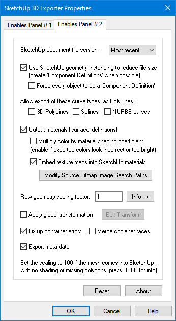
SketchUp document file version:
This combo box determines which SketchUp file version will be used to create the .skp file.Use SketchUp geometry instancing to reduce file size
SketchUp promotes the concept of geometry re-use via "Component Definitions". A component definition is a container of one or more 3D faces (polygons). The internal Okino 3D scene graph also uses a very similar, but more extensive concept, called "master objects" and instances whereby one geometry object can be instanced multiple times in a scene.If this checkbox is enabled (which is the default), then any Okino object definition which is instanced 2 or more times will be mapped into a SketchUp "Component Definition" and a corresponding number of "Component Instances". This will make for much smaller output files.
If this option is disabled then every internal instance will be expanded into a full, unique object inside SketchUp. Thus, 1000 instances of one common mesh object will be expanded into 1000 unique, copied meshes in the SketchUp file (and thus, taking up considerably more room).
Force every object to be a 'Component Definition'
Normally this exporter will only create a SketchUp "Component Definition" when the corresponding object inside the internal Okino scene graph has been instanced 2 or more times. This results in cleaner scenes to navigate inside the SketchUp user interface.However, if this option is enabled then each and every Okino scene graph object definition will be turned into a SketchUp "Component Definition", even if it is only instanced once in the scene. Why would you want to enable this option? It is useful is you envision creating more "Component Instances" of these exported "Component Definitions" inside of the SketchUp program. Rather than have to select the faces and create your own component definitions, they will already be created once the SketchUp file is loaded.
Allow export of these curve types (as PolyLines):
SketchUp only allows for 3D line segments. It does not have spline shapes or NURBS curves. The following options control how Okino's 3D curves are converted and output as PolyLines to the SketchUp file.3D PolyLines
If this checkbox is checkmarked then all 3D indexed line set primitives will be output to the SketchUp file as 3D PolyLines.Splines
If this checkbox is checkmarked then all 3D spline shape primitives (based on curves such as Bezier, B-Spline, Cardinal, Tension) will be converted to linear curves then exported to the SketchUp file as 3D PolyLines.NURBS curves
If this checkbox is checkmarked then all 3D NURBS curve primitives will be converted to linear curves then exported to the SketchUp file as 3D PolyLines.Output materials ('surface' definitions)
If this checkbox is checkmarked then materials will be exported along with any associated texture map.Multiply color by material shading coefficient
Inside Okino's internal scene graph each material has a "diffuse color" and a corresponding "diffuse shading coefficient". The "shading coefficient" can be considered a variable intensity control that brightens or darkens its corresponding diffuse color, without having to modify the color itself.If this checkbox is checkmarked then the diffuse shading coefficient is multiplied into its corresponding diffuse color value before being exported to the SketchUp file material.
If this checkbox is not checkmarked then only the raw diffuse color will be output to the SketchUp file and its corresponding shading coefficient value ignored. This will typically result in brighter, bolder and punchier materials, what we ourselves term "OpenGL" shading which tends to be more saturated than colors seen in photo-realistic rendering programs.
Embed texture maps into SketchUp materials
If this checkbox is checkmarked then a diffuse texture map associated with the material will be embedded directly inside the SketchUp file, attached to its corresponding material.In most cases you will need to press the "Modify Source Bitmap Image Search Paths" button and tell the exporter where your source bitmap textures are located.
Modify Source Bitmap Image Search Paths
In specific circumstances you will need to inform PolyTrans where your source bitmap images are located so that automatic bitmap file embedding process proceeds properly. If PolyTrans reports warnings that specific images could not be located during automatic bitmap conversion press this button so that the Search-Paths dialog box appears. Using this dialog box you can tell PolyTrans where your source bitmaps are located.Apply Global Transformation
If this checkbox is enabled then a general purpose global transformation will be applied to each exported scene. A new top-level grouping node will be added to the scene called "Global Transform" which will contain this new transformation matrix.This option will allow you to, for example,
- Re-center all of the geometry so that it is centered at the origin (0,0,0) in the SketchUp scene.
- Move all of the geometry so that it is sitting on the Y=0 (XZ) horizontal plane.
- Auto-scale the geometry so that it is no larger than a specific bounding box size.
- Scale the scene by a (X, Y, Z) value.
- Shear the scene by a (X, Y, Z) value.
- Rotate the scene by a (X, Y, Z) value.
- Translate the scene by a (X, Y, Z) value.
Fix up any container errors
This is a generic mechanism provided by the SketchUp software. It is enabled by default. It will examine the exported file and provide any necessary tweaks to it.Merge coplanar faces
This is a generic mechanism provided by the SketchUp software. It will automatically hide edges in the mesh if a series of adjoining polygons all sit in the same plane.Export meta data
SketchUp allows for "meta data" information to be defined per entity. Enabling this option will output such meta data to each entity.The following internal Okino scene graph meta data types are supported when exporting to SketchUp: strings, shorts, ints, floats, colors, vectors, double precision vectors, 4x4 matrices, 4x4 double precision matrices, time, double precision floats, 4 valued vectors, and 4-valued double precision vectors. All numeric values will be converted into meta data string for output to SketchUp.


