| You are here: Home » Import CAD Formats » PRC and 3D PDF |

This geometry import converter reads in native PRC 3D CAD files. It will also extract PRC and U3D files from within any chosen page of an Adobe 3D PDF file. It is an intelligent and well implemented importer for all forms of complex source PRC CAD file data, including the import and processing of 3D mesh and BREP (solids) geometry, assembly hierarchy (incl. intelligent “proto node” handling), materials (with adherence to the PRC father/son inheritance rules), 2D bitmapped texture maps, annotations and views markups, and all forms of PRC meta data.
In the grand scheme of things, and from Okino’s realistic perspective, this was written primarily as a targeted “legacy 3D file importer”. The lofty goals that Adobe had set out in 2004 to conquer the 3D MCAD market didn’t quite materialize and fizzled out by the late 2000’s and early 2010s. Hence, the key focus for this importer’s development was as a key tool to intelligently convert legacy 3D PDF file assets (with embedded PRC and U3D content) to other downstream applications such as 3ds Max, Maya, Cinema-4D, Unity, Unreal, VR head mounted devices, FBX, glTF/glB, etc., all of which Okino software supports very well.
Its primary focus is to provide an intelligent and automated “Load and Render” experience from any source PRC or Adobe Acrobat 3D PDF data.
Click on any one of the small screen snapshots to jump to the corresponding section of this WEB page:
| File Extraction | Main | Geometry | Optimizations |
|---|---|---|---|
![[1]](imp_prc_file_extraction_sml.gif) |
![[1]](imp_prc_main_sml.gif) |
![[2]](imp_prc_geometry_sml.gif) |
![[3]](imp_prc_optimizations_sml.gif) |
| Misc Options | Units Matching | Materials | Image Extraction |
|---|---|---|---|
![[4]](imp_prc_misc_options_sml.gif) |
![[4]](imp_prc_units_sml.gif) |
![[5]](imp_prc_materials_sml.gif) |
![[6]](imp_prc_imageextraction_sml.gif) |
PRC is probably one of the least known of 3D CAD file formats yet it forms the underpinning for Adobe Acrobat 3D PDF files. It may be considered the “silent younger brother of the more well known U3D file format”. It has a fairly long but little unknown history.
In very simple terms, PRC is a highly compressed 3D file format that facilitates the storage of different representations of a 3D CAD model (basically a 3D meshed version of a BREP solids CAD file) as well as embedded texture bitmap image files. It is little known or used within the 3D graphics market except for the fact that Adobe/Tetra4D came to replace/augment the U3D file format of Acrobat 3D PDF files with this PRC file format (roughly around 2010), primarily because PRC can retain BREP solids (NURBS) geometry items that the U3D file format cannot; however, the U3D file format has animation and skinning support that PRC does not.
As its little known origin story, the TTF company of France (Trade and Technologies) had originally created the PRC file format as its light weight visualization file format around 2002. When Adobe decided that it wanted to start competing with Autodesk for the MCAD market (for which it failed by ~2009), it chose to buy out the TTF company and its software assets in April 2006; PRC was one of those assets which Adobe came to acquire.
U3D was originally intended to be the main and primary 3D file format to be embedded within Acrobat 3D PDF files (as of the 2004-2007 era). Okino implemented one of the main + primary implementations of both U3D import and export, including animation and skinning support. Adobe’s interest (and of their 3D partners of the time) in U3D and 3D PDF dwindled down after 2009 (basically when they failed in their attempt to compete with Autodesk for the coveted MCAD market). Thereafter Acrobat 3D and 3D PDF was spun off to an independent company (Tetra 4D, 2010) which itself, and the related Adobe 3D PDF SDKs and TTF Group assets, were sold to Tech Soft 3D in 2013 for long term maintenance and support.
The PRC file format was approved as an international published open standard in 2014 (ISO 14739-1:2014).
- An intelligent 3D importer that can create highly efficient 3D models for downstream DCC/Animation, VisSim, VR/AR, file viewers and other modeling applications.
- Support for the extraction of PRC and U3D files embedded within Acrobat 3D PDF files. An interactive visual interface is provided which displays a list of the pages in which the PRC and/or U3D files were located within a 3D PDF file. Preview renderings can be viewed for selected PRC files prior to importing.
- Dynamic Tessellation of BREP (NURBS) geometry items. The PRC file format differs from the U3D file format by allowing BREP (NURBS) parametric CAD geometry items to be defined and embedded within the file. Most often the source CAD program will pre-tessellate these BREP geometry items and store them within the PRC file as a highly compressed 3D polygonal mesh. However, for the rare case when the source program stores just the BREP geometry and not a polygonal meshed variation, this importer will tessellate the BREPs to polygonal meshes during the import process with mesh density controllable via a UI option.
- Carefully implemented material and texture map handling. PRC files can often have complex 2D bitmap texture maps applied to the CAD objects. This PRC importer builds upon Okino’s 3 decades of experience with precise material and texture map conversion with the support of these PRC attributes:
- Material attributes: Diffuse color, Ambient color, Emission color, Specular color, Opacity, Reflectivity and Gloss factor (Phong shininess) with selectable “shading coefficient” overrides.
- Texture mapping methods: Diffuse color map, Specular color map, Emission color map, Bump map, Reflection map and Opacity map with support for UV repeat (scaling), UV offset and UV tiling parameters.
- The PRC importer has been tested on many files and carefully tweaked to produce ideal “load and render” imports of texture mapped objects.
- Material attributes: Diffuse color, Ambient color, Emission color, Specular color, Opacity, Reflectivity and Gloss factor (Phong shininess) with selectable “shading coefficient” overrides.
- Markups and annotations support whose entities are imported as accurate colorized polygonalized text and 3D polylines, grouped together as “3D PMI” or “Annotations Views”. Control is provided over hidden entity import.
- Import of ‘Views’ & Cameras, including orthographic and perspective cameras. Automatic scene fitting is done for PRC orthographic views.
- Automatic Texture Bitmap File Extraction of colormapped (8-bits), grayscale, RGB, BGR, RGBA and BGRA embedded image data to PNG disk-based files for use in downstream 3D programs for texture mapped objects.
- “Shading Coefficient Overrides” for the diffuse, ambient, emission and specular material colors, opacity value and the Phong shininess. These help to turn the “blown out” OpenGL shading model used by many PRC enabled applications into the more visually pleasing shading model used by common downstream DCC/Animation programs and viewers. This should allow for a quick “Load and Render” of the PRC model without having to spend an endless amount of time tweaking the imported material definitions.
- Four integrated CAD optimizers which take the most unwieldy and/or complex of PRC files and turns them into highly efficient models for all variety of downstream 3D programs and file viewers.
- Optimizer 1 locates and replaces all duplicated geometry.
- Optimizer 2 and 3 removes redundant runs of hierarchy tree nodes.
- Optimizer 4 invokes deep hierarchy tree node compression.
- Optimizer 1 locates and replaces all duplicated geometry.
- Imported node names can be selectively appended with the corresponding PRC entity’s Name, Prototype descriptor, Node ID and/or File System ID. This information can be useful for the downstream PRC viewer and/or for easier visual inspection.
- Geometry processing functionality ensures that the "faceted" polygonal geometry typical of PRC files gets cleaned up: vertex welding, vertex normals welding, UV texture coordinates welding, triangle to quad merging and automatic vertex normal creation (based on smoothing angle).
- Proper and intelligent units matching. For example, if a millimeter based PRC file is imported into 3ds Max (inches), then the scene will be automatically scaled appropriately. Millimeters are assumed if no explicit units override is found in the PRC file.
- Automatic scene scaling & re-centering functionality. The imported model can be automatically rescaled to a user definable size limit. Automatic re-centering of the model to the origin is optional for those common cases when the PRC model is located hundreds of thousands to billions of units from the origin (which is usually not numerically acceptable to downstream non-CAD 3D programs).
- Well implemented meta data import from all PRC scene graph nodes. Compliant to the PRC ISO specification.
- Two Tree Traversal Methods, based on either visiting all the children nodes first or visiting the PRC prototype nodes first. PRC is a bit odd in how some files are created and defined such that the same scene will not be identical if the hierarchy tree is traversed child-first vs. prototype-node-first. The default method will produce ideal PRC file imports.
This panel allows a specific PRC or U3D file to be extracted from the chosen Acrobat 3D PDF file. Selected PRC files can be optionally previewed in a shaded 3D rendering prior to import. This panel will only be shown if the source file is in 3D PDF format (.pdf file extension) and not when a PRC file is chosen for import.
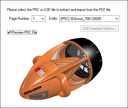
A 3D PDF file can contain one or more pages. Each page can contain an embedded PRC or U3D file. The “Page Number” drop-down combo box will list all pages found within the file and the “Entity” combo box will list whether a PRC or U3D file was found on that page. You can import, at most, one PRC or U3D file.
If you wish to preview the chosen PRC file then enable the “Preview PRC file” checkbox. No previews of U3D files are possible.
Caveat – If you enable the “Preview PRC file” checkbox then the next time you run the PRC importer it will create a preview image before the options dialog box is fully visible. Hence, if the PRC file to be loaded on the next execution of the importer is very large, that rendering and the start-up time to display the options dialog box may be slow. In such cases, disable the “Preview PRC file” checkbox before you start the PRC importer so that future executions will not have the file rendered prior to displaying the dialog box.
This panel contains the PRC import options which are most often used or should be considered during an import process.
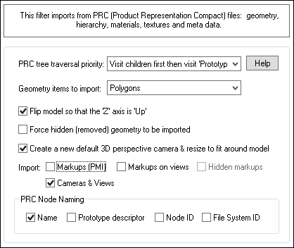
PRC tree traversal priority
This importer allows the hierarchy (tree) of PRC entities to be visited either by visiting all the children nodes first or visiting the PRC prototype nodes first. PRC is a bit odd in how some files are created and defined such that the same scene will not be identical if the hierarchy tree is traversed child-first vs. prototype-node-first.
For most cases you'll want to use the default option of 'Visit children first then visit Prototypes'. This will result in an error-free traversal of the PRC node tree.
However, in theory, a more optimal and compact 3D scene could be generated by using the second option of 'Visit Prototypes first then visit children'. This alternative will utilize Okino's 'red folder' instancing mechanism to replicate/simulate the instancing of entire sub-hierarchies as defined in the PRC file via its 'Prototype' nodes. As optimal as this method is, we have encountered at least one PRC file (an escalator with a lot of instancing) which had its transformation matrices missing beneath the 'Prototype' nodes. As such, we cannot guarantee that this alternative tree traversal method will result in an error free import process.
Geometry items to import: Polygons, Line Segments, Polygons & Line Segments
PRC files contain geometric visualization entities which are either 3D polygonal meshes and/or 3D poly-lines. This combo box allows you to choose which are to be imported. By default only polygonal meshes are imported.Flip model so that ‘Z’ axis is ‘Up’
Okino software uses a traditional “Y Up” coordinate system. MCAD and CAD programs, due to deep history, often use a “Z Up” coordinate system.If this checkbox is enabled then the Z-up coordinate system used by the imported PRC file will be automatically flipped so that all the data is in a Y-Up coordinate system.
As such, if you find that a 3D model appears “flipped on its side” upon import then please enable this checkbox and re-import the model.
Force hidden (removed) geometry to be imported
If this checkbox is enabled then geometry marked as “hidden” will be imported. This option is disabled by default. PRC files typically do not have hidden geometry items.Annotation and Markup Options
Import Markups and Annotations (3D PMI)
If this checkbox is enabled then markups and annotations will be imported as polygonalized text and 3D polylines, grouped together under a node labeled '3D PMI'.Note: this option only applies if no 'default view' has been defined in the PRC file. In such cases all markups and annotations defined in the PRC file will be blindly imported.
Note 2: You will also want to keep the "Import Markups and Annotations on Views" checkbox enabled as it will import the markups and annotations when a default view is specified.
If the “Report Statistics” checkbox option is enabled then the following statistics will be output:
Markups on Non-Annotations-Views = #
If and when no annotations or markups are imported from an associated PRC View (see next section below), this is the number of annotations or markups blindly imported from a corresponding Part Occurrence or Parts Definition.Markups tagged as 'No Show' = #
This is the number of annotations or markups marked as "No Show" in the PRC file. If the "Import hidden markups" UI option is enabled then these entities will be imported and set hidden else they won't be imported.If you also want the hidden entities to be imported then also enable the “Import Hidden Markups” checkbox.
Import Markups and Annotations on Views
This option is similar in scope to the 'Import Markups and Annotations' option except that it groups the markups and annotations found in the file based on their associated 'PRC View' nodes. Each grouping folder will be made hidden except for the one corresponding to the 'default view' as defined in the PRC file.If this checkbox is enabled then such markups and annotations, attached to PRC View nodes, will be grouped under a common node labeled 'Annotations Views' and then subsequent children grouping nodes named after each PRC View.
If there are no default views defined in the file then all of the markups and annotations grouped under the 'Annotations Views' folder will be set as hidden and a separate '3D PMI' folder will be created with all markups and annotations defined in the file if the 'Import Markups and Annotations (3D PMI)' checkbox is also enabled.
Need-to-know Information: In Adobe Acrobat the children of an 'Annotations Views' node don’t actually define explicit markups and annotations but rather make reference to pre-existing ones elsewhere (ie. the '3D PMI' Okino grouping folder). As you change from one view to another in Acrobat, these children references are toggled on and off to change their view-specific visibility. This functionality is not possible in Okino software and hence all of them are imported as 'hidden' by default except for the one defined as the current default view.
If the 'Report Statistics' checkbox option is enabled then the following statistics will be output:
Markups on Annotations-Views = #
This is the number of annotations and markups which were assigned and imported from specific PRC Views of a PRC Part Occurrence or Parts Definition.Markups tagged as 'No Show' = #
This is the number of annotations or markups marked as "No Show" in the PRC file. If the "Import hidden markups" UI option is enabled then these entities will be imported and set hidden else they won't be imported.Import Hidden Markups and Annotations
If this checkbox is enabled then markups and annotations tagged as being hidden will be imported rather than being ignored. However, they will remain in a hidden state within the imported scene.Force Import of all Markups
If this checkbox is enabled then all annotations and markups will be forcibly imported from the PRC file regardless of what display rules are being imposed on them. Such items may end up being duplicated in the imported scene.You should only enable this option if (1) the last file import reported 1 or more annotations/markups being found in the file but no annotations/markups appear and (2) you have tried specifying a specific View number to load but still no annotations/markups in the scene.
This option was added for a single 3D PDF file which defined 3 'Views' of which none were marked as being the 'Default View', and none of which made reference to any annotations/markups. This importer requires that annotations/markups be associated with one or more 'Views' to be imported, or, that one of the Views are marked as being the 'Default'.
Default View Number to Use/Import = #
PRC files can have zero or more “Views”. Each view is often associated with a different camera orientation, different annotations and markups, and different geometry transforms (such as used for “part explosions”).This type-in edit box determines which View number in the PRC file will be imported as the “default”.
A value of 0 (zero) causes the importer to use the View tagged as being the “Default View” in the PRC file itself.
A value of 1 or higher will import a specific view number to your own choosing. How can you best determine that number? After import all of the views found in the file will be listed in the Message Window and as such you can use the number from the left column, such as in this example:
View names found in the PRC file:
1 - 'Assembled'
2 - 'Exploded Line'
3 - 'Iso View'
You can also load up the PRC file into Adobe Acrobat and examine its Views combo box. The number to use in the Okino importer as the View number corresponds to the 1-based offset of the view name within that combo box.
PRC Node Naming: Name, Prototype Descriptor, Node ID, File System ID
These checkboxes define how the imported grouping and geometry node names will be “decorated”. You may find some of this additional decoration to be useful to differentiate one item from another.As an example, the following Okino instance node name is broken down as:
 Name = Latch Lever-4 Prototype Descriptor = Proto Ref Node ID = 533 File System ID = 27
Name
This is the name of the PRC entity.Prototype Descriptor
This will be displayed as “Proto Ref” if the node is a PRC prototype.Node ID
This is the unique instance ID of the PRC entity.File System ID
PRC files are segmented into “file structures” which can aid with the instancing of various entities. This is the ID of the related file structure that the PRC entity points to.
This panel controls how 3D geometry items (polygons and line segments) will be extracted and processed from the PRC file.
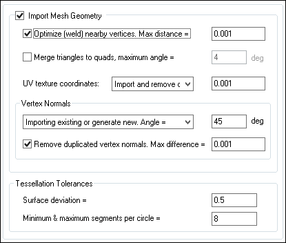
Import Mesh Geometry
This checkbox should not, in general, need to be disabled. It controls whether polygonal and poly-line data will be imported from the PRC file.Optimize (weld) nearby vertices. Max distance = ##
If this checkbox is enabled (check-marked) then the vertex welding operation will be applied to all polygon vertices once the PRC file has been read into memory and the objects created.Vertex welding collapses adjacent vertices which are within a distance less than or equal to the threshold value specified on the dialog box. Note that welding of vertices can only occur within a single object and not between different objects.
"Max distance" Type-In
If the distance between two vertices is less than or equal to this number, and the "Weld nearby vertices" checkbox is check-marked (enabled) then the two vertices will be collapsed (welded) into one.Merge triangles to quads, maximum angle = ##
This option is a post-processing step that merges triangles back to quadrilateral polygons (4 sided polygons). The number of vertices remain the same but the overall number of polygons are reduced.If this option is enabled (checkmarked) then an algorithm will be invoked which merges multiple polygons into quads. If two adjacent triangles are nearly co-planar then they will be turned into a quadrilateral. The vertices of the adjacent edges must be welded together (shared) for this operation to proceed properly.
The test for co-planar polygons (polygons which are almost on the same plane as each other) is determined by the "Max angle" type-in box. This value is measured in degrees. Values near 0 will require that adjacent polygons be very much co-planar with each other, while higher values will allow polygons that meet at an angle to be considered. For example, if you have a curved object made of triangles then try setting the angle to 4 to 7 degrees. Higher values will allow more polygons to be merged.
NOTE: you can also apply this merging algorithm via the "Polygon Processing" functionality found in the stand-alone Okino software. On that dialog box you would invoke the "Merge Co-Planar Polygons into larger polygons" function. That alternative version also provides some more controls over whether vertex normals, vertex colors and vertex uv’s are to be taken into account (they are all taken into account when invoked via the polygon reduction system).
UV texture coordinates:
If and when available, the UV texture coordinates will be imported along with the 3D polygonal mesh geometry. Please note that MCAD geometric entities defined in the PRC file such as BREP solids and NURBS surfaces might not have any UV texture coordinates assigned to them.
Do not import
If this combo box option is chosen then no UV texture coordinates will be imported.Import as-is
If this combo box option is chosen then the raw UV texture coordinates will be imported as-is.Import and remove duplicated coordinates
If this combo box option is chosen then the raw UV texture coordinates will be imported and then any replicated coordinates removed based on the maximum difference between them defined by the type-in value. This value is in the “coordinate system of the UV texture values” or “UV space”.Vertex Normals
Vertex normals are 3D vectors which point away from the vertices of each polygonal mesh object. These vectors help a destination 3D program render an otherwise faceted mesh object as smooth. It is these vertex normals which can make a faceted sphere render as looking entirely smooth. If a model does not have any vertex normals then the geometry will look all faceted and not smooth.The following options aid with the import of the vertex normals and/or the automatic computation of new vertex normals for a geometry item.
Combo box operation:
Do not import
If this combo box option is chosen then no vertex normal coordinates will be imported.Import existing values
If this combo box option is chosen then any existing vertex normal coordinates defined within the PRC file will be imported as-is.Generate new values = ##
If this combo box option is chosen then brand new vertex normals will be computed for a mesh model. This will be purely a “best guess” approximation based on how smooth the geometry is.The smoothing criterion is based on the angle between abutting polygons; common smoothed vertex normals will be computed if the angle between their geometric surfaces normals is less than the angle specified on the dialog box (which defaults to 45 degrees).
In general you will want to use a smoothing angle of (roughly) 15 degrees to 60 degrees. However, 45 degrees is a safe bet.
Import existing or generate new values = ##
This combo box option is similar to the last two combined together.If the imported polygonal mesh data has existing, explicit vertex normals then they will be used as-is. However, if the mesh data has no existing explicit vertex normals then new ones will be computed in the manner explained in the “Generate new values” section.
Remove duplicated vertex normals. Max difference = ##
This is the same as the 'Optimize (weld) nearby vertices' function except that it combines redundant vertex normals that are within a certain numerical threshold of each other.Tessellation Tolerances
The PRC file format differs from the U3D file format by allowing BREP (NURBS) parametric CAD geometry items to be defined and embedded within the file. Most often the source CAD program will pre-tessellate these BREP geometry items and store them within the PRC file as a highly compressed 3D polygonal mesh. However, for the rare case when the source program stores just the BREP geometry and not a polygonal meshed variation, this importer will tessellate the BREPs to polygonal meshes during the import process with mesh density controllable via a UI option.Surface deviation = 0.5
This value determines how smooth the tessellated BREP solids and/or NURBS surfaces will be once that they are turned into a polygonal mesh. Smaller values will create larger number of polygons and hence a finer quality mesh.Minimum & maximum segments per circle = 8
This value controls how fine a circle will be tessellated during import. In most cases this value, and such a tessellation procedure, will never be used during a PRC file import.
Miscellaneous Options Panel
This panel provides some miscellaneous options.
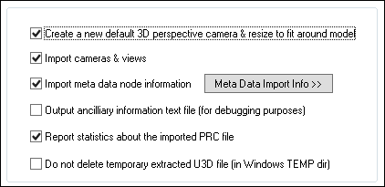
Create a new default 3D perspective camera & resize to fit around model
PRC files do not always define a 3D perspective camera. As such, a blindly imported PRC file may not show up in the most ideal location within the default camera’s viewport.If this checkbox is enabled then a new Okino-specific 3D perspective camera will be created and made the "default" camera. The camera will be arbitrarily zoomed out to view the entire imported PRC model.
Import Cameras and Views
If this checkbox is enabled then 3D Orthographic and Perspective Views/Cameras will be imported.Import meta data node information
A key aspect of the PRC file format is the “meta data” (properties) associated with each node in the file.
Such meta data can be viewed within the stand-alone Okino software via the “Meta Data” tool window (located in the lower right corner of the UI) and via the “Meta Data” panel of the Instance Attributes editor (which is accessible by right clicking on an Instance name in the upper-right Selector Window and choosing the ‘Edit instance attributes’ menu item).
The extraction and conversion of the meta data is compliant to the PRC ISO specification.
NOTE:
If you wish to import meta data while the 'Compress and optimize number of objects' checkbox is enabled on the 'Optimizations' panel, you will need to change the following importer processing option so that certain “redundant” instance nodes will not be unnecessarily deleted:
- Press the 'Edit Options...' button located to the right of the 'Compress and optimize number of objects' checkbox on the 'Optimizations' panel.
- Press the 'Hierarchy Options...' button located to the right of the 'Optimize hierarchy after completion' checkbox.
- Enable the checkbox for 'Meta data associated with it' on the 'Folder Hierarchy Optimizer' options dialog box."
Output ancillary information text file (for debugging purposes)
If this checkbox is checkmarked then additional verbose information about the source PRC file will be saved to a text file located in the directory from where the PRC file was loaded. The file will have “- Info.txt” appended to the original PRC filename. In general you will not need to look at this file.Report statistics about the imported PRC file
If this checkbox is checkmarked then statistics will be output after the PRC file has been imported, which looks like this:PRC file parsing statistics: Mesh Totals: Polygons = 172942 Vertex coordinates = 518826 Vertex indices = 518826 Vertex normals = 518826 Vertex texture coordinates = 31896 Objects = 35 Materials = 36 Texture definitions = 5 Extracted raster images = 2
This panel controls which form of scene & instance-node optimizations will be performed on the import PRC data.
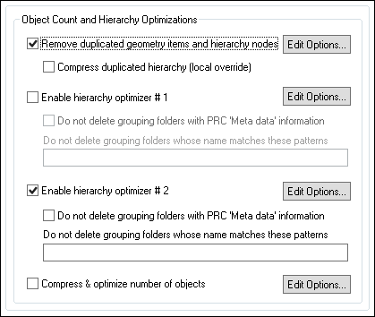
Remove duplicated geometry items and hierarchy nodes
This option is enabled by default as it will locate and find duplicated items within an imported PRC scene. For example, if the optimizer locates 1000 copies of a PRC entity then it’ll replace those explicit copies with a single geometry definition pointed to by 1000 reference (“1000 instances of a single Okino master object geometry definition”).Note that this optimizer is equivalent to running the “Remove duplicated geometry/hierarchy via re-instancing algorithm” command from within the Okino stand-alone software, from the “Win” menu of the upper-right Selector Window.
There is extensive online help for this command by pressing the “Edit Options…” button and then the Help button on the dialog box which appears.
Compress duplicated hierarchy (local override)
This checkbox is a 100% local override to the exact same-named option found on the optimizer’s “Edit Options…” dialog box. In other words, the state of this local checkbox entirely overrides the one shown on the optimizer’s dialog box.
If you want the most optimal of imported PRC files then go and enable it.
Enable hierarchy optimizer # 1, Enable hierarchy optimizer # 2
These options provide methods to remove redundant hierarchy nodes ("NULLs", or grouping folders) from the imported file.
- Optimizer #1 removes runs of empty folders, as well as folders with no children. This is disabled by default.
- Optimizer #2 is simpler, deleting empty folders which only have 1 geometry object in them. This is enabled by default.
These options can also be enabled via the "Optimize hierarchy after completion" checkbox found on the options dialog box of the "Compress & optimize number of objects" option (see below).
Do not delete grouping folders with PRC 'Meta data' information
PRC grouping folders and geometry nodes most often contain a LOT of meta data information (which is imported along with the node from the PRC file itself).By default (when this checkbox is disabled), the optimizer will be allowed to delete such redundant grouping folder nodes, regardless of whether there is any meta data information on them or not.
However, if this checkbox is enabled then the redundant grouping folder will not be allowed to be deleted by the optimizer if it is found that there is meta data information on it.
The choice of whether to allow such redundant grouping folders to be deleted is up to yourself and whether you need access to every imported node of the PRC file which has had valid meta data information associated with them.
Note: this local PRC-centric checkbox completely overrides the corresponding checkbox (“Meta data associated with it”) found on the optimizer’s main options dialog box (which is accessible via the “Edit Options….” button).
Do not delete grouping folders whose name matches these patterns
There may be cases when you may not want specific grouping folders to be deleted during the optimization process.This text type-in box contains a list of pattern matching strings. If any grouping folder’s name matches one or more of these pattern matching strings then that folder will not be deleted.
Each pattern matching string is separated from the next one by a comma.
Note: this list of strings supplements/appends-to (and does not override) the list of pattern matching strings found on the optimizer’s options dialog box.
The syntax of the pattern matching string is defined as follows:
- 1. * matches any sequence of zero or more characters,
- 2. ? matches any single character,
- 3. [SET] matches any single character specified by the SET, where any other character other than the minus sign or the close bracket may appear in the set. A set is composed of characters or ranges; a range is indicated by two characters separated by a minus sign, such as in 0-9 or A-Z.
[0-9a-zA-Z_] is the minimal set of characters allowed in the [SET] pattern construct. Other characters are allowed (ie. 8 bit characters) if your system will support them.
[!SET] or [^SET] matches any character not in the specified set.
- 4. To suppress the special syntactic significance of any of '[]*?!^-\', and match the character exactly, precede it with a '\'.
The following are example pattern matching strings:
*		Matches everything
?		Matches all one character strings
???		Matches all three character strings
*test		Matches '1test', 'thisisatest', 'test'
t*s*t		Matches 'test', 'tesseract'
[a-z]s*t		Matches 'asset'
s[!gh]t		Matches 'set'
s[!e]t		Doesn't match 'set'
[a-fh-z]*		Matches 'jack', 'flack', 'zoom'
i\**		Matches 'i*guess'
[\[-\]]		Matches '[' and ']'
[a-z\\]		Matches a, b, c, \
Compress & optimize number of objects
This checkbox enables one of the most important and critical scene processing functions in all of Okino software. It is an integral and core part of any Okino CAD importer, and it has been added to the PRC importer for added benefits.The primary purpose of this function is to walk the imported geometry hierarchy and compress together all objects that are parented under a single folder into a one new object. For example, if you import a PRC file and find that 200 polygonal objects are grouped under one folder, then enabling this option will cause all such occurrences to collapse the children geometry of each grouping folder into one object.
Note that this optimizer is equivalent to running the “Optimize Scene – Number of Objects & Folders” command from within the Okino stand-alone software, from the “Win” menu of the upper-right Selector Window.
The documentation for this option can be viewed by pressing the "Edit Options…" button and then the "Help" button on the optimizer's dialog box.
This panel controls (1) units matching, (2) automatic re-centering and (3) scene scaling.
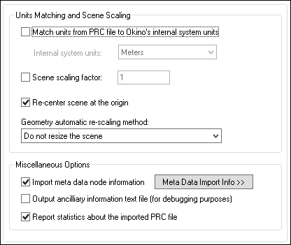
Match units from PRC file to Okino's internal system units
CAD files most often have an associated “unit of measure” such as meters, feet, inches, etc. Thus, a raw value of “1.0” can then be considered and tagged as “1.0 meters”However, when these models are imported into another 3D package that uses a different unit of measure then a "units conversion" needs to occur. For example, Maya uses cm, 3ds Max and SketchUp use inches by default, LightWave uses cm or meters, MicroStation uses mm, etc. This happens by applying an internally computed scale factor to all of the imported 3D coordinates data.
If this checkbox is enabled then the PRC importer will rescale all imported geometry so that the units of the PRC file can be made to match the units of the current internal Okino database. If the checkbox is disabled then the geometry will be imported unchanged and untouched, meaning that its scale may be "incorrect".
PRC uses millimeters as its default unit of measure if none is specified in the file.
Internal System Units
This drop-down combo box specifies the current units system in effect within the internal Okino 3D database. It defaults to meters. What you need to do is select an appropriate entry from the drop-down combo box which matches the system units used by your destination program: for example, set it to Centimeters for Lightwave, Inches for 3ds Max, Centimeters for Maya, etc.
None No units; never do any geometry scaling Custom Custom units are in effect. See below Microinches 1e-6 inches Mils 1e-3 inches Inches 0.0254 meters Feet 12 inches Miles 63360 inches Microns 1e-6 meters Millimeters 1e-3 meters Centimeters 1e-2 meters Meters Kilometers 1e+3 meters Scene scaling factor - ##
This value allows a custom scaling to be applied to the overall imported scene.For example, if set to 10.0 then the imported scene will be scaled 10 times larger. If set to 0.1 then the imported scene will be scaled 10 times smaller.
Re-center scene at the origin
If this checkbox is enabled then the scene will be re-centered at the origin, based on the overall bounding box of the imported scene.It is common for CAD models to be geo-located and hence end up being hundreds of thousands to billions of units away from the origin. Why is this bad? Well, very few or no 3D users are aware of our common daily explanation. Many source MCAD modelers using double precision floating point numbers which have 16 digits of very high precision. However, almost all downstream programs that you’ll take your PRC files into only use single precision floating point numbers with a lowly 6 digits of numerical precision. What that means is that these destination programs do not have the numerical fidelity to encode a number such as “1,000,000.1234” as the .1234 portion will be chopped off. We have seen MANY cases of an AutoCAD user placing a house (which is only 0.1 units across) many millions to billions of units away from the origin, then wondering why their model implodes to a dot when converted to a non-MCAD program.
As such, this option brings the model back to the origin where it should retain more numerical precision.
Geometry Automatic Rescaling Method
This combo box provides access to a useful mechanism which automatically rescales the imported mesh geometry to a size best needed by other 3D software packages. This combo box can be used to automatically resize any imported model data to a useful size, such as scaled to easily fit inside a box of 2x2x2 raw working units (which is the default). The various options are described as follows:Do Not Resize the Scene
No resizing is done to the imported data.Resize to 1x1x1 units
Resize to 2x2x2 units>
The model data is automatically scaled up in size, or scaled down in size so that its worldspace extents fits inside a 1x1x1 or 2x2x2 sized unit cube. The latter is the default.Resize to User Defined Absolute Size
The model data is automatically scaled up in size, or scaled down in size so that its worldspace extents fit inside a cube whose size is user defined by the type-in value shown on the dialog box. For example, if you enter the value 20 then the imported data will be resized so that its maximum extent in one or more dimensions is 20 units.Scale Larger by User Defined Factor
Scale Smaller by User Defined Factor
These options allow the imported model data to be scaled larger or scaled smaller by an absolute number. For example, if you select the ‘larger’ option and enter 10 into the type-in box, then the imported model will be scaled 10 times larger during the import process.
This panel controls the processing and optimization of PRC material definitions and their related 2D texture maps.
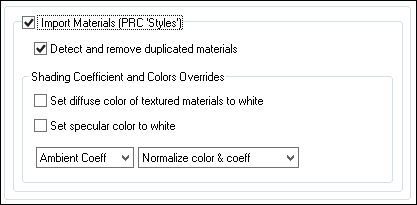
Import Materials
If this checkbox is checkmarked then visual/rendering attributes of each PRC geometric entity will be imported as Okino surface (material) definitions:
- Material attributes: Diffuse color, Ambient color, Emission color, Specular color, Opacity, Reflectivity and Gloss factor (Phong shininess) with selectable “shading coefficient” overrides.
- Texture mapping methods: Diffuse color map, Specular color map, Emission color map, Bump map, Reflection map and Opacity map with support for UV repeat (scaling), UV offset and UV tiling parameters.
Detect and remove duplicated materials
If this checkbox is checkmarked then only unique material (surface) definitions will be created. The uniqueness will be achieved by comparing all imported visual attributes and texture maps attributes.Set diffuse color of textured materials to white
This is one of those options that may come in handy for someone with particular requirements for their textured objects in the PRC file.If this checkbox is checkmarked then any material which has a diffuse texture map assigned to it will be output in such a way that its diffuse surface color will be set to white.
This is useful because certain real-time renderers use an "OpenGL" shading model in which the diffuse color is multiplied into the assigned texture map colors - if the diffuse material color is dark or black then the texture map will not be visible (often a problem when exporting from Maya for which the diffuse surface color is always set to black for textured materials). Enabling this option will cause the diffuse surface color to become white, and thus it will not affect the brightness of the assigned texture map.
If this checkbox is not checkmarked then the diffuse surface color will be imported unchanged.
This option can be enabled in case texture maps look too bright or washed after being imported from the PRC file.
Set specular color to white
If this checkbox is enabled then the specular material color will always be set to white (although, the white can be dimmed by changing the 'Specular Coefficient' material parameter override, as described above). If disabled, then the real material's specular color will be imported.Shading Coefficient and Colors Overrides
These combo box options allow the various imported material attributes to be fine tuned or outright modified. The two combo boxes and the single numeric text box provide good control over the ambient, diffuse, specular, opacity and shininess shading coefficients imported from the PRC file.Note: PRC revolves around an “OpenGL-like” shading model for which the diffuse and specular colors will be 100% saturated. When imported and rendered in a visualization program (such as Autodesk Maya, Autodesk 3ds Max, etc.) they will look washed out and super-saturated. As such, these combo boxes are preset to set the diffuse to 40% and specular to 70% of their imported colors; by doing so the imported PRC model should be in a “load and render” state.
The first drop-down combo box selects which of these shading parameters is to be modified. Each shading coefficient has its own operation that can be selected (via the second combo box) and an optional numeric text value (via the third data entry text input box). The following describes the various shading parameters that can be controlled:
- Ambient Coefficient: This controls the amount of color reflected from an object based on the ambient light in a scene. A good default value is 0.1 through to 0.3 and ideally ranges from 0.0 to 1.0.
- Diffuse Coefficient: This controls the amount of color reflected from an object based on the direct light shining on it. A good default value is 0.4 and ideally ranges from 0.0 to 1.0.
- Specular Coefficient: This controls the intensity of the highlight color on an object. A good default value is 0.7 and ideally ranges from 0.0 to 5.0.
- Luminous Coefficient: This controls how much color is added directly to an object, irrespective of any light which shines on it (the higher the value, the more the object will appear to glow). In general you should keep this value at 0. If an export file format does not support a luminous shading coefficient then this value will be multiplied into the luminous shading color itself.
- Opacity: This is the inverse of transparency. 0.0 will make the object fully transparent, while at 1.0 the object will be fully opaque.
- Phong Shininess: This controls the width of the specular highlight seen on an object. An ideal range is 6 (very wide) to 300 (very narrow). The default is 32.
For each material shading parameter, several actions can be performed on each material shading parameter during the import process:
- Do Not Import: The shading parameter is not imported at all. No value is imported nor sent to the Okino software. Thus, the default material shading parameter value (as set inside Okino software) will be used instead.
- Import Unchanged: The shading parameter is imported as is, with no change.
- Set and Use Default: The shading parameter is set to some "good" default value (as determined by the import converter). This default value will be shown in the type-in box.
- Set to Specific Value: The imported shading parameter will be overridden with the user specified value of the numeric type-in box.
- Import and Crop by: The shading parameter is imported and will remain unchanged if it is less than the numeric type-in value shown on the dialog box. If it is greater, then the imported value will be clamped to be no greater than the numeric type-in value. This is a good operation, for example, if you do not wish for the ambient shading coefficient to be greater than 0.3.
- Import and Scale by: The shading parameter is imported and multiplied by the numeric type-in value shown on the dialog box
This panel controls how embedded bitmap texture images are extracted from a PRC file as PNG disk-based files.
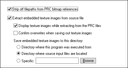
Strip off filepaths from PRC bitmap reference
A PRC texture map may (rarely or ever?) provide a Url Reference to a bitmap texture image. If this checkbox is checkmarked then any prefix or file path will be stripped off of the bitmap filename itself. It is enabled by default.Extract embedded texture images from source file
PRC allows for bitmap texture images to be embedded within a file (which tends to be the norm).If this checkbox is checkmarked then colormapped (8-bits), grayscale, RGB, BGR, RGBA and BGRA embedded image data will be extracted to PNG disk-based files for use in downstream 3D programs for texture mapped objects.
Display texture images while extracting from the PRC files
If this checkbox is checkmarked then the embedded images will be displayed as they are being processed.Confirm overwrites when saving out texture images
If this checkbox is checkmarked then you will be prompted if an existing bitmap image on disk is about to be overwritten. However, that should never occur as the PRC bitmap extractor will always create unique filenames.Save embedded texture images to this directory:
These radio buttons determine where the extracted bitmap images will be saved to.Directory where this program was executed from
This option will save the bitmap images to the same directory from where the Okino software was executed from.Directory where source input files are located
This option will save the bitmap images to the directory from where the PRC file was loaded from.Specific
This option will save the bitmap images to the user specified directory. Press the “Browse” button to select a new directory location.

