| You are here: Home » Import CAD Formats » NGRAIN's 3KO Solutions |
|
The AutoCAD DXF and DWG geometry export converter writes out the scene database as either 3-point or 4-point polygons using the 3DFACE or PolyFace mesh entities. Polygons with 5 or more vertices, concave polygons, or polygons with holes are automatically triangulated.
Important Note: For most of the last 30 years the only primary way to move data back into AutoCAD has been with DXF or DWG files. However, more recently, AutoCAD can now import, via its 'atf' framework, from a number of industry standard 3D file formats. Hence, out of that list, you could export from Okino software and into AutoCAD using FBX, JT, Rhino 3dm and Microstation DGN files.
Please also refer to the corresponding DXF/DWG import converter.
If the file is written using the PolyFace mesh option then there is no need to weld the geometry data when the DXF file is read into another program (since the data output to the DXF file will be automatically welded by this converter).
DWG and binary DXF output is only available when the Okino "CAD/Pack license" has been purchased since it uses a third party licensed DWG technology toolkit. When the CAD/Pack license is not purchased, output will be in DXF ASCII R12 format.

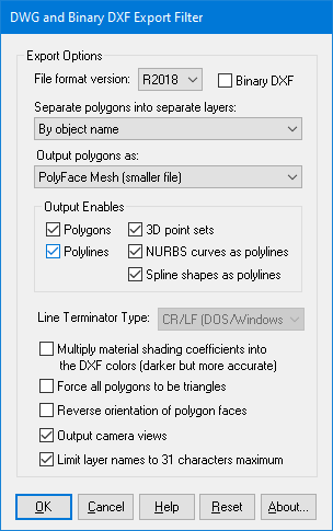
The following information explains the various options on the dialog box:
File Format Version
When exporting to DWG format, or binary DXF, this combo box determines which version of the file format will be used. R12 is the most general and widespread version of the DXF/DWG file format, while any others from the list would be newer versions of the file format.Separate Polygons Into Separate Layers
This option determines which layers each polygon will be assigned to:By Object Name
All polygons belonging to a single object will exported to its own DXF layer with the layer’s name being derived from the object’s handle name. This is the default.By Surface Name (Material Name)
All polygons that share the same surface name (material name) will be exported on the same DXF layer. The layer name will be derived from the surface name.One Layer
All polygons will be exported to a single DXF layer named “LAYER1”.Output Polygons As...
This option determines whether polygons will be exported using the DXF PolyFace mesh entity or the 3D FACE entity:PolyFace Mesh (smaller files)
Polygons will be exported using the DXF PolyFace Mesh (PFACE) entity. This creates a more compact DXF file and can be read in much faster than a file written using the 3D FACE entity. All polygons are stored in two arrays consisting of a vertex array list and a face list.In AutoCAD you can use the PEDIT command to stretch, rotate, scale and move the mesh but not to edit it. To edit the faces, use the EXPLODE command to break the mesh into separate 3D Face entities.
NOTE: Files written using this entity type already have their vertices automatically welded by this program’s export utility.
3D FACEs (larger files, more common)
Polygons will be exported using the DXF 3D FACE entity. This creates much larger files since each polygon is stored to the file one-by-one. However, most DXF reader programs can read this format so it might be necessary to use this option if a DXF reader cannot understand the PolyFace Mesh format.Output Enables
These checkboxes control which geometric entity types are allowed to be exported to the DXF/DWG file.Multiply Shading Coefficients into the DXF colours
Inside Okino's internal scene graph each material has a "color" and a corresponding "shading coefficient" for each ambient, diffuse, specular and luminous color definition. The "shading coefficient" can be considered a variable intensity control that brightens or darkens its corresponding color, without having to modify the color itself.If this checkbox is checkmarked then the 'diffuse' shading coefficient will be multiplied into its corresponding diffuse color value before being output to the DXF/DWG file as an 'AutoCAD Color Index' (ACI value). Sometimes this makes an exported scene look too dark within AutoCAD and hence it has been disabled by default.
If this checkbox is not checkmarked then only the raw diffuse RGB color will be output to the DXF/DWG file. This will typically result in brighter, bolder and punchier materials in the destination program.
Force all Polygons to be Triangles
If this checkbox is check-marked then all polygons will be saved to the DXF file as triangles. By default it is not check-marked so the polygons are saved to the file as either 4-sided quadrilaterals or 3-sided triangles.Reverse Orientation of Polygon Faces
If this checkbox is check-marked then the orientation of the polygon faces will be revered. This might be necessary if the destination program which reads in the DXF file requires a different polygon orientation than used by this program.Output Camera Views
If this checkbox is enabled then the current orthographic and perspective cameras in the internal database will be output to the DXF file as "VIEW" records in the "TABLES" section.Limit Layer Names to 31 Characters Maximum
If this checkbox is enabled then all layer names will be truncated to a maximum of 31 characters. This option is enabled by default to be compatible with versions of AutoCAD that only work when layer names are 31 characters in length or less. If this checkbox is not enabled then the layer names will not be truncated.

