| You are here: Home » Import CAD Formats » NGRAIN's 3KO Solutions |
|
This export converter (an integral aspect of Okino's core software) outputs clean and detailed files to the X3D, Classic VRML, VRML 2.0, VRML 1.0 and a sub-set of the Open Inventor v2 file formats. VRML2, Classic VRML and X3D are probably three of the most common and standardized 3D file formats currently in existence. The Okino VRML/X3D import/export converters form the backbone of our software products and allow 3D data to be transferred between most 3D software products. Some people have been misled to believe VRML2 is an obsolete "WEB streaming" file format but in fact VRML2/X3D are the main industry 3D standardized file formats. This exporter is extremely well developed and robust.
Other related links on the Okino WEB site:
- Output of clean mesh data with optional vertex normals and vertex
texture coordinates.
- Lights (point, spot and directional) and the perspective camera.
- 3D indexed line sets and 3D point sets
- Embedding of any form of texture image inside a VRML file as raw data,
or just providing the reference to the texture file.
- Automatic bitmap conversion and automatic bitmap resizing to/from the
most popular 2d bitmap file formats.
- Modification controls for bitmap file paths written to the VRML file.
- Material parameter output: ambient color, diffuse color, specular color,
emissive color, shininess and transparency.
- Proper segmentation of a mesh into multiple mesh primitives so that
diffuse texture maps can be assigned properly.
- Compression using gZip
- Hierarchy for geometry and folders ("null nodes" or "empty
instances/objects").
- Export of Object, camera, light and material animation.
- Vertex colors for mesh data.
- The usage of DEF/USE of the VRML2 file specification to allow instancing
of geometry. This can greatly reduce the size of an exported VRML2 file if
one mesh, or a sub-set of a VRML hierarchy tree is referenced multiple times.
- NURBs surfaces with trim curves (using the Blaxxun NURBS template style)
- 3D NURBS curves
- Output in a XML format (X3D XML mode)
- Indexed triangle strip geometry
- NURBs surfaces with trim curves (NURBS or linear trim curves)
- 3D NURBS independent curves
- Control over the conversion of NURBS curves to NURBS or linear curves in the output file, or conversion to meshes or NURBS surfaces if the curve(s) are closed.
- Control over the conversion of Spline Shape primitives to NURBS or linear curves in the output file, or conversion to meshes or NURBS surfaces if the curve(s) are closed.
- Polygons with holes will be triangulated before being output as indexed
polygon primitives.
- Since there is no ambient light type in the VRML specification the
ambient light color is multiplied into each material's ambient color (VRML
1.0 only).
- Normals and texture coordinates are bound on a per-vertex basis, while
materials are bound on a per-face (per-polygon) basis.
- If multiple textures are assigned to a single object then that object
will be exploded into separate indexed polygon primitives before being output
to the VRML file, with each primitive being assigned a single texture.
- Note that this converter does not allow anchors or inlines to be output
along with the data. These commands can be inserted into the file manually.
- As with all other export converters, the exported indexed polygons are
automatically welded and optimized before being output to the VRML file.
This optimization includes removing redundant coordinates and creating
vertex normals if none exist. Thus, the exported geometry should be in a
good, compact form for efficient VRML usage.
- Blaxxun NURBS templates are only available in VRML/2.0 format and not X3D or Classic VRML.
Animation is exported such that 'Transform' nodes have 'PositionInterpolator' or 'OrientationInterpolator' nodes routed to them (Transform nodes describe the scale, rotation and translation transformations). These interpolators must be routed from a 'TimeSensor' node. The 'Transform' node's scale, rotation, and translation fields are supported for animation, whereas scaleOrientation and center fields are not.
Animation data is exported as follows: A TimeSensor's 'fraction_changed' event-out is routed to a PositionInterpolator or OrientationInterpolator's 'set_fraction' event-in. The TimeSensor creates fractional values from 0.0 to 1.0 (corresponding to its cycle time) which are used to interpolate values in the subsequent interpolators. The interpolator's 'value_changed' event-out is then routed to a Transform node's 'set_translation', 'set_rotation', or 'set_scale' event-in field. The hierarchy is as follows:
TimeSensor, Output = fraction_changed (value from 0.0 to 1.0) --> PositionInterpolator, Input = set_fraction, output = value_changed --> Transform node, Input = set_translation, or set_rotation, or set_scale.
- Since a Transform's scale field is a SFVec3f, a ScalarInterpolator
cannot be used with this export converter. Scaled key framed animation will
be exported with the PositionInterpolator as a scaling interpolator.
- Interpolator's key fields will always vary from 0.0 to 1.0.
- The ROUTE statements are output at the end of the file.
- The TimeSensor node is output just before the ROUTE statements at the
end of the file.
- All Interpolator nodes are output as children nodes of the Transform they are routed to.
The following sample shows the animated translation of a box. A TimeSensor, Box01-TIMER, is routed to a PositionInterpolator Box01-POS-INTERP, and this is routed to the Transform node Box01. The TimeSensor has a loop enabled and will restart at the end of the interval, which is every 10 seconds. The box moves along the path interpolated by the position interpolator.
#VRML V2.0 utf8 DEF Box01 Transform { translation -158.1 -85.02 92.16 rotation -1 0 0 -1.571 children [ DEF Box01-TIMER TimeSensor { loop TRUE cycleInterval 10 enabled TRUE } DEF Box01-POS-INTERP PositionInterpolator { key [ 0 0.33 0.66 1 ] keyValue [ -158.1 -85.02 92.16, -131.6 -85.02 31.07, 142.9 -85.02 101.7, 146 -85.02 109.5, ] } Shape { appearance Appearance { material Material { diffuseColor 0.5686 0.1098 0.6941 } } geometry Box { size 59.9 24.15 55.07 } } ] } ROUTE Box01-TIMER.fraction_changed TO Box01-POS-INTERP.set_fraction ROUTE Box01-POS-INTERP.value_changed TO Box01.set_translation
The following information explains the various options on the dialog box:
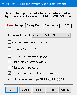
File Format to Export
This option determines which VRML file format is to be used to export the data:
- VRML 1.0 - This is the original VRML file format which is actually a subset of the Inventor file format. The syntax of the file format is rather different than that of VRML 2.0.
- VRML 2.0 - This is the most popular and widespread version of the VRML file format. When selected, hierarchy, animation, a head light, vertex colors, DEF/USE for geometry, 3D trimmed NURBs surfaces (Blaxxun style) and materials can also be output to the VRML 2.0 file. This is the default option.
- Inventor 2.0 (Subset) - If selected, this will output an Inventor v2.0 file using VRML 1.0 syntax in which case the header will be changed to "#Inventor V2.0 ascii" instead of " #VRML V1.0 ascii" and the file extension will be .iv instead of .wrl. This is not a full implementation of the Inventor file format but rather only than part defined by the VRML 1.0 specification (since VRML 1.0 is a proper subset of the Inventor file format).
- X3D - This is newer XML successor to the VRML2 file format. It is XML based, ASCII. Basically all of the VRML2 export capabilities are mirrored to the X3D exporter.
- Classic VRML - This is newer successor to the VRML2 file format and is the flip-side complement to the X3D file format. The syntax for the file is almost identical to that of VRML 2.0 format. However, Classic VRML is required if you wish to output NURBS surfaces, tri-strips or NURBS curves, as well as any newer component definitions which are no longer supported as part of the original VRML2 file format syntax.
Write Files to a New Directory
If this option is enabled (checkmarked) (which is the default) then a new directory will be created into which will be stored all of the .wrl VRML files and any automatically converted bitmap files. The directory name will be derived from the selected export filename. If this option is not enabled then no directory will be created.Enable a "Head Light" (VRML 2.0, X3D and Classic VRML only)
If this option is enabled (checkmarked) then the "headlight" field in the VRML 2 or X3D file will be set to TRUE in the "NavigationInfo" node. When viewed in a VRML browser, a light will always shine from the location of the viewer into the scene.Reverse Orientation of all Polygons
If this option is enabled (checkmarked) then the orientation of all polygons will be reversed (this will effectively swap the orientation of the polygons geometric normals).Triangulate Concave Polygons
If this option is enabled (checkmarked) then all concave polygons will be triangulated before being output to the .lwo object files. This option is disabled by default which will allow concave polygons to be output to the .wrl file.Triangulate All Polygons
If this option is enabled (checkmarked) then all polygons will be triangulated before being output to the .wrl file. This option is disabled by default. Please note that this option overrides the previous Triangulate Concave Polygons option if it is enabled.Line Terminator Type
This common option selects which line terminator is to be used for the ASCII output file:
- Files destined for DOS/PC machines should use CR/LF,
- Files for UNIX machines should use LF, and
- Files for Macintosh machines should use CR.
The default is specific to which machine this converter is presently running on: CRLF for DOS/PC, LF for UNIX and CR for Macintosh. This option normally does not have to be specified unless you will be using the exported ASCII file on a different type of computer.
This dialog box allows referenced bitmaps (of the internal 3D scene database) to be automatically converted to other 2d bitmap formats during the export process.
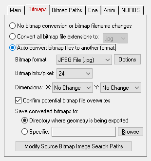
The three options available are:
- Do not modify the bitmap filename reference and do not perform any bitmap conversion.
- Modify the extension of the bitmap filename to a bitmap format (chosen from a drop-down list) but do not perform any bitmap conversion. This option is useful if you have (1) either performed the bitmap conversions in a previous export process or (2) you wish to use an external program (such as PhotoShop) to perform the bitmap conversions.
- Perform bitmap conversion and change the file extension of the bitmap. For example, if your original 3D scene data referenced JPEG bitmaps, but you want the exported VRML file to reference GIF bitmaps, then this option can be used to automatically convert the JPEG files to GIF and change all bitmap references to the new GIF files.
No Bitmap Conversion or Bitmap Filename Changes (Radio Button)
If this radio button is chosen then any bitmap reference exported into the VRML file will not be changed, its filename extension wont be changed, the path to the bitmap will not be changed and no bitmap conversion will be done.Convert all Bitmap File References To... (Radio Button)
Rather than convert referenced bitmap images to another file format this radio button (when selected) simply changes all the file extensions on bitmap files to a specific type. For example, if set to GIF then all bitmap filenames exported to the VRML file will be changed so that their file extensions end in .gif. This is a useful option is you already have all of the referenced texture maps converted to the desired file format (either from a previous invocation of this export converter or by using a batch bitmap conversion program).Auto-Convert Bitmap Files to Another Format (Radio Button)
If this radio button is selected then all 2d bitmap textures which are currently defined and referenced by the internal NuGraf/PolyTrans database scene will be automatically tagged then converted to a new user-specified 2d bitmap file format during export. The desired format is chosen using the Bitmap File Format combo box. If the texture(s) cannot be found in the location specified by the pathname prepended to the input texture filename then the export converter will search for the texture(s) in all directories specified in the Default Search Path and the Texture Bitmaps Search Path file search paths (these can be modified by choosing the Preferences/Configure File Search Paths menu item.Bitmap File Format (Combo Box)
This combo box lists the destination bitmap file format. The default is GIF format which is commonly used by VRML browsers (JPEG is another common bitmap format).Bitmap Bits/Pixel: 2, 4, 8, 24 (Combo Box) Dimensions: X = #, Y = #Confirm Potential Bitmap File Overwrites
If this checkbox is check-marked then the program will not prompt for confirmation of potential file overwrites (this is the default). If this option is disabled then the program will first prompt for confirmation of any file overwrites.Save Converted Bitmaps To...
These radio buttons determine where the new bitmap file will be written to. Note that the options shown on the "Bitmap Paths" dialog box panel may change the path prefix for the converted bitmap even though it was saved to disk in the location specified by one of these 2 radio buttons.Directory Where Geometry Is Being Exported
The new bitmaps will be written to the directory where the VRML file is being exported to.Specific + Browse
The new bitmaps will be written to the directory specified by the text box. This directory can be changed by press the Browse button.
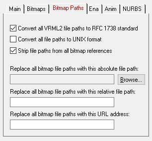
Convert all VRML file paths to RFC1738 Standard (VRML 2.0, X3D and Classic VRML only)
Since bitmap file paths are written to a VRML file using the "url" command it is important to enable this option when writing bitmap file paths to VRML 2 files. If this option is enabled (checkmarked) then all bitmap file paths written to the VRML 2 file will be converted into the "RFC 1738" URL format specification. This option will override the "Convert all file paths to UNIX format" when enabled. However, the conversion to RFC1738 will not be done when a valid string is specified for the "Replace all Bitmap File Paths With This URL Address" option below (since it is assumed the URL address string specified is already in RFC1738 format). As examples:C:\polytrans\bitmaps\texture.tif --> file:///C|/polytrans/bitmaps/texture.tif
\\machine\polytrans\bitmaps\texture.tif --> file:////machine/polytrans/bitmaps/texture.tif
Convert all file paths to UNIX format
If this option is enabled (checkmarked) then all bitmap file paths written to the VRML file will be converted to a UNIX compatible format (it will not take effect for VRML2 files if the "Convert all VRML2 file paths to RFC1738 Standard" option is enabled). In particular, all DOS-specific backward slashes \ will be converted to UNIX forward slash / directory separators. Also, any DOS-like drive specifiers, such as c:\ will be removed from the file path and a warning message will be reported about the removal of this drive specifier (you should make sure that all DOS-like drive specifiers be replaced by UNC specifiers, such as \\machine1\). If this option is disabled then no conversions will be made.Strip File Paths from All Bitmap References
If this option is enabled (checkmarked) then any file paths on a bitmap reference will be stripped off. For example, "C:\polytrans\bitmaps\texture.gif" will be output as "texture.gif".Replace all Bitmap File Paths With This Absolute File Path:
This option allows all bitmap references exported to the VRML material file to be prefixed with a new filepath. This might be useful, for example, if all of your bitmap files are located in one specific directory or if you wish to change the prefix on the imported bitmap references. This new path will override all other options on this bitmap conversion dialog box (in other words, it will replace a bitmaps file path regardless of any other file path added to the bitmap via other options in this dialog box). To choose the filepath press the Browse button. To disable this option type any character into the "Replace all Bitmap File Paths With This URL Address" type-in line, then delete that character.Replace all Bitmap File Paths With This Relative File Path:
This is the same as the previous "Replace all Bitmap File Paths With This Absolute File Path" option except that you can specify any arbitrary file path by typing the text into the type-in field. Whereas the previous method only allowed absolute file paths (ie: "C:\polytrans\bitmaps\texture.gif"), this option allows for relative file paths (ie: "bitmaps\texture.gif"). To disable this option, delete all text in the type-in field.Replace all Bitmap File Paths With This URL Address:
If this option is enabled (checkmarked) then all bitmap filenames (used in association with a texture map) will be prefixed with the string specified in the URL type-in. For example, if a texture references the filename 'c:\files\textures\bitmap.tif' within this programs database, and the URL is specified on this dialog box as 'http://www.okino.com/images/' then the bitmap filename will be stored in the VRML file as 'http://www.okino.com/images/bitmap.tif'.
The following options control what is sent to the VRML file:
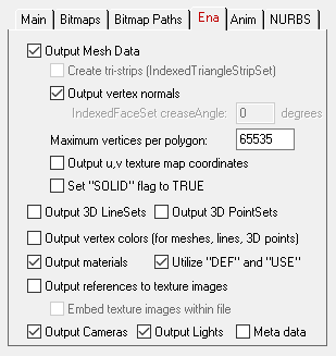
Output Mesh Data
If this checkbox is enabled (checkmarked, which is the default) then the raw mesh data will be output to the VRML file along with the following optional attributes:Create Tri-Strips (IndexedTriangleStripSets) (X3D and Classic VRML only)
Enabling this option for X3D or Classic VRML creates an optimized "triangle strip set" which in many cases should render the exported data faster in dedicated X3D + Classic VRML viewers such as Octaga, Xj3D and Blaxxun Contact.The polygon data is first triangulated and then "long strips" of triangles are created internally before being exported to the "IndexedTriangleStripSets" geometric primitive.
Output Vertex Normals
This option outputs normals and normal indices for all the polygon data (i.e. IndexedFaceSet) If you do not choose this option, no normal data will be exported and the 'creaseAngle' field for IndexedFaceSet will be used by a vrml browser to determine how normals are generated. This option is enabled by default.IndexedFaceSet Crease Angle (VRML 2.0, X3D and Classic VRML only)
This value is only valid if the "Output Normals" checkbox is disabled and VRML2 or X3D output is enabled. The 'creaseAngle' field for an IndexedFaceSet determines how default vertex normals are generated by the VRML browser. These vertex normals create the illusion of the geometry being smooth when shaded. If the angle between two adjacent polygons is less than the Crease Angle value then the seam between the two polygons will appear smoothed; if the angle is greater than the crease angle then a sharp seam will appear between both polygons. Input values are taken as degrees. The default is 0 (no smoothing), but good values are in the range 30 to 50 degrees for nice smoothing.Maximum Vertices Per Polygon
This type-in box determines the maximum number of vertices allowed per polygon. In most cases you will not need to modify this parameter. The default is 65535 which means "no limit on the number of vertices per polygon". If you set this type-in to a specific value, say 5, then if any mesh has polygons with 5 or more vertices that entire mesh will then be triangulated prior to output.Output u,v Texture Map Coordinates
If this option is enabled (checkmarked) then (u,v) texture mapping coordinates will be output to the VRML file for those primitives which reference 2d textures. If disabled (uncheckmarked) then no texture mapping coordinates will be output. These texture coordinates define how a 2d bitmap image is to be mapped onto the 3d geometric primitive.Set "SOLID" Flag to TRUE (VRML 2.0, X3D and Classic VRML only)
This option will output the 'solid' field as TRUE in all the IndexedFaceSet geometry. The solid field determines whether one or both sides of each polygon shall be displayed in a VRML browser. If solid is FALSE, each polygon shall be visible regardless of the viewing direction (i.e., no backface culling shall be done, and two-sided lighting shall be performed to illuminate both sides of lit surfaces). If solid is TRUE, back faces of polygons will not be visible in the browser. This option is disabled by default (i.e. solid is FALSE) Enable this option if you know you do not want to see back faces of polygons and want to dramaticatically increase navigation, viewing, and animation performance in a vrml browser. A susbstantial increase in speed is possible for large files since the browser does not have to render both sides of the polygons.Output 3D LineSets
If this checkbox is enabled (checkmarked, which is the default) then 3D line geometry will be output as an "IndexedLineSet" primitive.Output 3D PointSets
If this checkbox is enabled (checkmarked, which is the default) then groups of 3D points will be output as the "PointSet" primitive.Output Vertex Colors (for meshes, lines and 3D points) (VRML 2.0, X3D and Classic VRML only)
If this option is enabled (checkmarked) then vertex colors and color indices will be output to the VRML file for those primitives which have assigned vertex colors (meshes, lines and 3D points). If disabled (uncheckmarked) then no vertex colors and color indices will be output.NOTE: Since meshes are output using the "IndexedFaceSet" primitive type to the VRML file, the 'color' and 'colorIndex' fields will be used to define the vertex colors and the 'colorPerVertex' field will be set to 'TRUE'.
Output Materials
If this option is enabled (checkmarked) then materials and their related parameters will be output: ambient color, diffuse color, specular color, emissive color, shininess and transparency.Utilize "DEF" and "USE" For Material Definitions (VRML 2.0, X3D and Classic VRML only)
This option will allow materials to be named with the DEF keyword so that they may be referenced by name later in the file with the USE keyword whenever an identical material is encountered. This option avoids duplicate redefinition of materials and reduces file size.Output References to Texture Images
If this option is enabled (checkmarked) then texture mapping references will be output to the VRML file for those primitives which references 2d textures; VRML 1 will use the "filename" keyword before each bitmap reference and VRML2 will use the "url" keyword. If disabled (uncheckmarked) then no texture mapping references will be output.Embed Texture Images Within File
If this option is enabled (checkmarked) then any texture images referenced by the VRML data will be embedded directly within the VRML file.Output Cameras
If this option is enabled (checkmarked) then a perspective camera definition will be output to the VRML scene with the following attributes: position, orientation, focal distance and hieght angle.Output Lights
If this option is enabled (checkmarked) then point, spot and directional lights will be output.Output Meta Data
If this option is enabled (checkmarked) then meta data will be output to X3D and Classic VRML2 files. Meta data is optionally associated with the Okino global scene and nodes on instances, objects and others such as materials. Global scene meta data will be output on the firstnode in the exported file. Meta data will be output as float, double, int or string metadata nodes.
The following options control hierarchy and animation export to VRML, X3D and Classic VRML files.
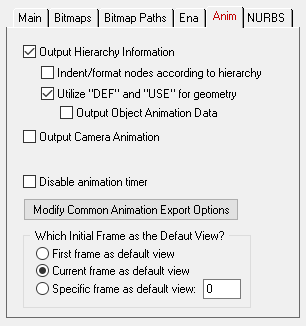
Output Hierarchy Information (VRML 2.0, X3D and Classic VRML only)
If this option is enabled (checkmarked) then transformation hierarchy will be output to the VRML file. Exporting the hierarchy will preserve 'Transform' nodes and allow for easier hand editing and visual inspection of grouped nodes in the VRML file. If disabled (uncheckmarked) then the 'Transform' node hierarchy will not be output and all geometry will be translated to the root level node. This checkbox must be enabled in order to output animation to the VRML2 file.Indent/Format Nodes According to Hierarchy (VRML 2.0, X3D and Classic VRML only)
This option will indent nodes written to the .wrl file corresponding to the current hierarchy level. The purpose of this option is to allow easier hand editing of the .wrl file and to provide the ability to directly see the hierarchical structure of the nodes in the file. It is enabled by default.Disable this option if you are dealing with very large scenes with thousands of polygons and you want to reduce file size dramatically by removing these indentations. For example, if you have several nested 'Transform' nodes in a scene, this option will nest the 'Transform' nodes in the output file as in this example:
"Indent Nodes enabled"
DEF MyTransform1 Transform { children [ DEF MyTransform2 Transform { children [ DEF MyTransform3 { children [ Shape { geometry { Box { } } } ] } ] } ] }"Indent Nodes disabled"
DEF MyTransform1 Transform { children [ DEF MyTransform2 Transform { children [ DEF MyTransform3 Transform { children [ Shape { geometry { Box { } } } ] } ] } ] }Utilize "DEF" and "USE" for Geometry (VRML 2.0, X3D and Classic VRML only)
If this option is enabled (checkmarked) then the DEF and USE keywords of the VRML2 specification will be used to implement raw object instancing; for example, if a single raw mesh is used 1000 times (tranformed appropriately) in a scene, then this option allows the raw mesh data to be defined only once (DEF) but referenced multiple times (USE). Thus only 1 copy of the raw mesh data is needed in the VRML file instead of 1000 raw copies; hence, the file size can be much smaller.Technically, the 'Transform' nodes encapsulating geometry ('Shape' nodes) will be pre-fixed with the DEF keyword. This will allow the geometry (Shape) nodes to be referenced by name throughout the file with the USE keyword whenever an identical Shape node is encountered. This option avoids duplicate redefinition of 'Transform' nodes containing geometry and significantly reduces file size.
If disabled (uncheckmarked) then the DEF and USE keywords will not be output. Instead, each 'Transform' node will be output in full each time it appears in the scenegraph (ie. mesh geometry will be duplicated). NOTE: This option must be enabled in order to output animation data.
Output Object Animation Data (VRML 2.0, X3D and Classic VRML only)
If this option is enabled (checkmarked) then object animation data will be output if it is present. Specifically, 'OrientationInterpolator' and 'PositionInterpolator' nodes and ROUTE statements will be output. A 'TimeSensor' node to run the animation will also be output. If disabled (uncheckmarked) no 'TimeSensor', ROUTE statements, or Interpolator nodes will be output. The "Output Hierarchy Information" and "Utilize "DEF" and "USE" for Geometry" options must be enabled in order to enable this animation option.Output Camera Animation Data (VRML 2.0, X3D and Classic VRML only)
If this option is enabled (checkmarked) then camera animation data will be output if it is present. Specifically, 'OrientationInterpolator' and 'PositionInterpolator' nodes and ROUTE statements will be output. A 'TimeSensor' node to run the animation will also be output. If disabled (uncheckmarked) no 'TimeSensor', ROUTE statements, or Interpolator nodes will be output. For camera animation, the position, orientation and field-of-view is exported (in addition, the position and orientation keyframe lists are always resampled).Output Light Animation Data (VRML 2.0, X3D and Classic VRML only)
If this option is enabled (checkmarked) then point, spot and directional light animation data will be output if it is present.Output Material Animation Data (VRML 2.0, X3D and Classic VRML only)
If this option is enabled (checkmarked) then material animation data will be output if it is present.Disable Animation Timer (VRML 2.0, X3D and Classic VRML only)
This option sets the 'enabled' field to FALSE in the TimeSensor node; the TimeSensor node controls the overall animation timing. Enabling this option (so that the timer is disabled) is useful if you desire to export animation data to the .wrl scene file but you do not want the animation to begin playing when the the scene file is loaded into the VRML browser. You may manually edit the .wrl file and enable the timer by setting the 'enable' field to TRUE in the TimeSensor when you wish to enable animation.Modify Common Animation Export Options
Pressing this button will display the Common Animation Export Options dialog box. This dialog box controls how internal animation data is optionally re- sampled during its export to a VRML file.Which Initial Frame as the Default View?
The following radio buttons determine which frame of an animation will be output to the VRML file as the default, non-animated view. This is useful either when (1) the VRML animation timer is explicitly disabled and you want to specify which animation frame will be seen by default, or (2) animation export is disabled but you wish to output a specific animation frame to the VRML file anyway.First Frame as Default View
This option will export the very first frame in the animation as the initial default view of the scene. If there is no animation data present or the "Output Animation" checkbox is disabled then the current view in NuGraf's camera viewport is exported.Current Frame as Default View
This option will export the frame in the animation that is currently being viewed as the initial default view of the scene. This is useful if you do not want animation data output but want to export the frame that is currently being viewed. If there is no animation data present, the current view in Nugraf's camera viewport is exported.Specific Frame as Default View
This option will export the specified Nth frame in the animation as the initial default view of the scene. This is useful if you do not want animation data output but want the Nth frame exported. If there is no animation data present, the current view in Nugraf's camera viewport is exported.
The following options control NURBS surface and curves export.
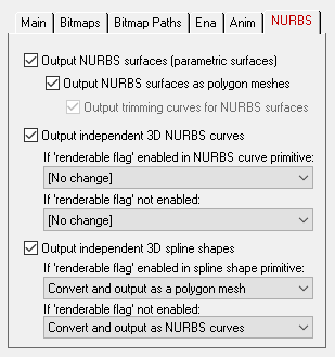
Output NURBS surfaces (parametric surfaces)
If this checkbox is checkmarked then trimmed NURBS surfaces will be exported, either in raw form or as converted polygon meshes. The NURBS surface options are only enabled for VRML2, Classic VRML and X3D modes.Note: In VRML2 mode the NURBS surfaces are output in the older "Blaxxun" template style.
Output NURBS surfaces as polygon meshes
If this checkbox is checkmarked then the raw trimmed NURBS will be tessellated into a polygon mesh prior to export. If it remains uncheckmarked then the raw trimmed NURBS data will be exported directly.Output trimming curves for NURBS surfaces
If the above option is disabled (pure NURBS output enabled) then this checkbox determines whether trim curves will be output along with the parent trimmed NURBS surfaces. Trim curves define the outer boundary of a NURBS patch as well as specifying internal trim holes and islands.Output independent 3D NURBS curves
These options are only enabled for Classic VRML and X3D modes.The NuGraf/PolyTrans 3D database has a very extensive NURBS curve sub-system. Each NURBS curve object can have 1 or more NURBS curves associated with it. Multiple curves inside a single object can either be considered to form a single continuous "composite" curve, or each curve can be considered unique, closed, planar (in world space) and oriented such that the curves of the object can be directly converted into a trimmed NURBS surface (in other words, the first curve forms the boundary of the surface and subsequent closed curves form the holes).
The following options control how the various NURBS curve configurations can be converted during the export phase. An extensive internal NURBS curve conversion and cross-conversion system exists.
If 'renderable flag' enabled in NURBS curve primitive:
If the 'renderable' flag of a NURBS curve primitive is internally enabled, and the curve(s) form closed loops, then it is possible to convert the NURBS Curve primitive into a 3D format that is renderable: either a meshor a trimmed NURBS surface. The following options define what will be done to NURBS Curves primitives during the export phase when their 'renderable' flag is enabled:[No Change]
No change. The NURBS Curve primitive will be exported as-is.Convert and Output as Polygon Mesh
The NURBS Curve primitive will be converted into a mesh object prior to export.Convert and Output as Trimmed NURBS Surface
The NURBS Curve primitive will be converted into a corresponding trimmed NURBS surface (patch). If the conversion process cannot be made then it will be output as a polygon mesh instead.If 'renderable flag' not enabled:
If the 'renderable' flag of a NURBS Curve primitive is not enabled then the curves will be considered just as plain curves that cannot be seen when rendered. In this case, the following options define what will be done to NURBS Curves primitives during the export phase when their 'renderable' flag is disabled:[No Change]
No change. The NURBS Curve primitive will be exported as-is.Output Composite NURBS Curve as a Single Curve
No change except in the case when the NURBS curve primitive is defined as a single composite curve made up of multiple curve segments. In this case the multiple curve segments will be temporarily converted to a single NURBS curve before export.Convert and Output as Indexed Polylines
Each NURBS curve is resampled into a corresponding set of linear polylines and output as 2-point lines. The final linear polyline will look similar (within an error tolerance) to the original NURBS curve.Output independent 3D spline shapes
These options are only enabled for Classic VRML and X3D modes.The NuGraf/PolyTrans 3D database has a very extensive spline primitive sub-system. This primitive accommodates one or more spline curves per primitive. If the multiple spline curves are each closed then the overall Spline Shape is termed "renderable" and can be thus converted into a polygon mesh or a corresponding trimmed NURBS surface (patch). For example, the letter "B" can be defined by 3 Bezier curves, the first forming the outer boundary and the latter two forming holes. Note, that unlike the NURBS Curve primitive, each spline curve of the Spline Shape is composed of only a single curve segment (no composite spline curves are allowed).
The following options control how the various Spline Shape configurations can be converted during the export phase. An extensive internal Spline Shape conversion and cross-conversion system exists. The Spline Shape primitive also handles almost every major spline type (Bezier Spline, B-Spline, Cardinal Spline, Linear Spline, Tensioned Spline, TCB Spline), and their internal cross conversion (between spline types) or between the various spline types and a NURBS curve.
If 'renderable flag' enabled in spline shape primitive:
Convert and Output as Polygon Mesh
The Spline Shape primitive will be converted into a mesh object prior to export.Convert and Output as Trimmed NURBS Surface
The Spline Shape primitive will be converted into a corresponding trimmed NURBS surface (patch). If the conversion process cannot be made then it will be output as a polygon mesh instead.If 'renderable flag' not enabled:
Convert and Output as a NURBS Curve Object
Each spline curve of the Spline Shape primitive is resampled into a corresponding NURBS Curve segment and placed into a single NURBS Curve primitive. The 'renderable' flag of the new NURBS Curve primitive will be disabled. The final NURBS Curve primitive will look similar (within an error tolerance) to the original Spline Shape.Convert and Output as Indexed Polylines
Each spline curve of the Spline Shape primitive is resampled into a corresponding set of linear polylines and output as 2-point lines. The final linear polyline will look similar (within an error tolerance) to the original Spline Shape.

