| You are here: Home » Import CAD Formats » IFC |

This geometry import converter reads in native IFC files of versions Ifc2x3, Ifc4, Ifc4x2 or newer. It is a very complex importer along the lines of our extensively developed STEP, ProE/Creo, DGN and DWF-3D importers (among others).
Its primary focus is to provide an intelligent and automated “Load and Render” experience from any source IFC data.
Needless to say, the IFC file format is steeped in decades-long history and is rather complex to interpret correctly. This IFC importer goes a long way to take the raw elemental nature of IFC data and turn it into a clean + succinct form.
Click on any one of the small screen snapshots to jump to the corresponding section of this WEB page:
| Main | Geometry | Optimizations |
|---|---|---|
![[1]](imp_ifc_main_sml.gif) |
![[2]](imp_ifc_geometry_sml.gif) |
![[3]](imp_ifc_optimizations_sml.gif) |
| Units Matching | Materials | Image Extraction |
|---|---|---|
![[4]](imp_ifc_units_sml.gif) |
![[5]](imp_ifc_materials_sml.gif) |
![[6]](imp_ifc_imageextraction_sml.gif) |
The Industry Foundation Classes (IFC) data model is intended to describe architectural, building and construction industry data.
It is a platform neutral, open file format specification that is not controlled by a single vendor or group of vendors. It is an object-based file format with a data model developed by buildingSMART to facilitate interoperability in the architecture, engineering and construction (AEC) industry, and is a commonly used collaboration format in Building information modeling (BIM) based projects.
IFC files can be written out by such industry standard programs as: ArchiCAD, Allplan, Autodesk's AutoCAD and Revit, Tekla Structures, SmartPlant3D and Vectorworks. Please note: you would always want to use the DWF-3D file format and the Okino DWF-3D file importer to import 3D model data from Autodesk's AutoCAD, Navisworks and Revit, as well as AVEVA's PDMS software.
The IFC model specification is open. It is registered by ISO and is an official International Standard ISO 16739-1:2018.
It is may be safe to say that few 3D graphics users properly understand IFC or why/how it should be used, when it should be used or how it is to be used. In simplistic terms, IFC is NOT a universal data interchange file format like COLLADA, FBX, 3ds, OBJ, DXF, DWG, etc.
Rather, IFC is more of an "abstraction" for an architectural model so that BIM companies can exchange IFC files for design iterations without any loss in overall geometric quality. Hence, the basis of IFC is to make an abstract building with stories, floors, doors, columns, windows, etc., each with their original explicit design criteria. From these hang "abstractions" such as 2D plan views and 3D renderable geometric data. The geometric data itself can have different representations such as BREP solids (MCAD) geometry, 3D polygonal meshes, 3D polylines, 3D point sets, etc.
While IFC can be considered a standardized file format by BuildingSmart, not all 3D programs or 3D viewers will "interpret" an IFC file in the same manner due to the abstract nature of the file format and also by the generally loose manner in which a model can be defined and with different contexts and representations.
The IFC initiative began in 1994, when Autodesk formed an industry consortium to advise the company on the development of a set of C++ classes that could support integrated application development.
In 1997 the “International Alliance for Interoperability” was reconstituted as a non-profit industry-led organization, with the goal of publishing the Industry Foundation Class (IFC) as a neutral AEC product model responding to the AEC building lifecycle. A further name change occurred in 2005, and the IFC specification is now developed and maintained by buildingSMART.
IFC1 = 1997, IFC1.5 = 1998, IFC2.0 = 1999, IFC2x2 = 2003, IFC2x3 = 2006, IFC4 = 2013, IFC4.1 = 2018, IFC4.2 = 2019.
IFC2x3 is currently the most widely supported version of IFC and the most stable.
- An intelligent 3D importer that can restructure and optimize the imported IFC data structures, in a variety of ways, to produce an ideal and highly efficient 3D model for downstream DCC/Animation, VisSim, VR/AR, file viewers and other modeling applications.
- Support for .ifc, .ifcXML and .ifcZIP variations of IFC file encoding, of versions Ifc2x3, Ifc4, Ifc4x2 or newer.
- The Okino IFC importer is not based on freeware or open-source IFC SDKs as almost all others are.
- Intelligent handling of IFC visual attributes (such as RGB color, opacity and highlight intensity) and the correct mapping of “IfcStyle”, “IfcSurfaceStyle” and “IfcMaterials” over to distinct Okino surface (material) definitions.
- IfcSurfaceStyleLighting, IfcSurfaceStyleRefraction, IfcSurfaceStyleShading and IfcSurfaceStyleWithTextures are supported for visual attribute assignments.
- Supported visual attributes include: Diffuse Color, Reflection Color, Specular Color, Transparency, Specular Highlight, Specular Exponent, Specular Roughness, Reflectance Method (Phong or Blinn) and Refraction Index.
- “Shading Coefficient Overrides” for the diffuse and specular material colors, opacity value and the Phong shininess. These help to turn the “blown out” OpenGL shading model used by many IFC enabled applications into the more visually pleasing shading model used by common downstream DCC/Animation programs and viewers. This should allow for a quick “Load and Render” of the IFC model without having to spend an endless amount of time tweaking the imported material definitions.
- The support for 2D bitmap texture mapping is rather poor or non-existent for IFC enabled applications within the architecture, engineering and construction (AEC) industries. However, Okino has implemented extensive bitmap texture mapping support throughout its IFC importer for future days when IFC files are more commonly written with such integrated and embedded texturing data:
- The 3 main texturing methods which are supported from IfcSurfaceTexture are IfcImageTexture, IfcPixelTexture and IfcBlobTexture. The texture modulation methods supported are: Texture, Bump, Opacity, Reflection, Self Illumination, Shininess, Specular and Transparency mapping. Automatic bitmap extraction is also supported for IfcPixelTexture and IfcBlobTexture.
- Four integrated CAD optimizers which take the most unwieldy, complex and nasty of IFC files and turns them into highly efficient models for all variety of downstream 3D programs and file viewers.
- Optimizer 1 locates and replaces all duplicated geometry.
- Optimizer 2 and 3 removes redundant runs of hierarchy tree nodes.
- Optimizer 4 invokes deep hierarchy tree node compression.
- Flexible restructuring of the IFC data model. The model can be optionally imported with or without its spatial (not relational) node hierarchy tree. Physically based building elements (such as IfcBeam, IfcColumn, IfcDoor, IfcStair, IfcWall, IfcWindow) can be split out into their own hierarchical folders for ease of inspection. Elemental nodes can also be regrouped into their own grouping folders based on their IfcPresentationLayer (display layer) associations.
- Imported node names can be selectively appended with the corresponding IFC entity’s Class Name, Name, Description, ID and/or Global ID (GUID). This information can be useful for the downstream IFC viewer and/or for easier visual inspection.
- Geometry processing functionality ensures that the "faceted" polygonal geometry typical of IFC files gets cleaned up: vertex welding, vertex normals welding, UV texture coordinates welding, triangle to quad merging and automatic vertex normal creation (based on smoothing angle).
- Proper and intelligent units matching. For example, if a millimeter based IFC file is imported into 3ds Max (inches), then the scene will be automatically scaled appropriately.
- Automatic scene scaling & re-centering functionality. The imported model can be automatically rescaled to a user definable size limit. Automatic re-centering of the model to the origin is optional for those common cases when the IFC model is located hundreds of thousands to billions of units from the origin (which is usually not numerically acceptable to downstream non-CAD 3D programs).
- Well implemented meta data import from the IfcProject node, the IFC file’s header and each child node.
This panel contains the IFC import options which are most often used or should be considered during an import process.
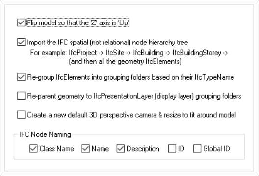
Flip model so that ‘Z’ axis is ‘Up’
Okino software uses a traditional “Y Up” coordinate system. MCAD and CAD programs, due to deep history, often use a “Z Up” coordinate system.If this checkbox is enabled then the Z-up coordinate system used by the imported IFC file will be automatically flipped so that all the data is in a Y-Up coordinate system.
As such, if you find that a 3D model appears “flipped on its side” upon import then please enable this checkbox and re-import the model.
Import the IFC spatial (not relational) node hierarchy tree
This is an important option to keep enabled.IFC files are highly hierarchical by definition and as such enabling this option will ensure that the hierarchy tree of the IFC entities are recreated during the import process.
For example, many IFC files are structured in this manner
IfcProject
        IfcSite
                IfcBuilding
                        IfcBuildingStorey
                                And then all the geometry IfcElements
The following screen snapshot shows such a spatial node hierarchy:
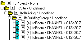
If this checkbox is disabled then all of the IFC entities will be imported in a flat hierarchy.
Re-group IfcElements into grouping folders based on their IfcTypeName
Each physical building element within an IFC file is defined by a “Type Name”. Example type names are:IfcBeam, IfcColumn, IfcDoor, IfcFurnishingElement, IfcStair, IfcSlab, IfcWall, IfcWindow, etc.
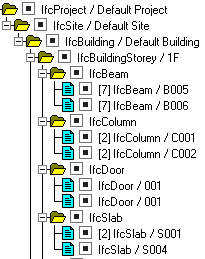
If this checkbox is enabled then the imported hierarchy of IFC physical building elements, that use the same Type name, will be regrouped under a common grouping folder. This will result in a much tidier hierarchy tree and one which is easier to navigate visually.
The following screen snapshot shows how the IFC elements have been regrouped by their corresponding IfcBeam, IfcColumn, IfcDoor and IfcSlab types.
Re-parent geometry to IfcPresentationLayer (display layer) grouping folders
In many or most CAD programs will be the concept of a “CAD Layer” or a “CAD Level”. These are used to group geometric entities together for easier access and/or override control.Okino software does not allow geometric entities to be placed in a node hierarchy and a CAD layer at the same time, and as such this option was provided.
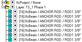
If this checkbox is enabled then any IFC entity which is associated with a IfcPresentationLayer will be “yanked” out of its hierarchy tree location and placed into its own explicit, named CAD layer (or “Yellow grouping folder” in Okino terminology). You will most likely find that the hierarchy tree becomes bear or empty when this option is enabled.
In general terms, you will not want to enable this option. It was provided for generality sake and to allow for some form of IfcPresentationLayer support.
The following screen snapshot shows how the IFC entities have been reparented to a new presentation layer grouping folder named “TS_1 Phase 1”:
IFC Node Naming: Class Name, Name, Description, ID, Global ID
These checkboxes define how the imported grouping and geometry node names will be “decorated”. You may find some of this additional decoration to be useful to differentiate one item from another.As an example, the following Okino instance node name is broken down as:
 Class Name = IfcBeam Name = Anchor Rod Description = RODI 3/8” ID = 3836 Global ID = 1EzDHo0011AJ4pCZGsDp0n
Class Name
This will use the pruned IFC SDK class name from which the entity was derived. For example, the full class name of “OdIfc2x3::IfcProject” (for IFC 2x3) will use “IfcProject” as the first part of the node name.Name
This is the name of the IFC entity.Description
This is the description associated with the IFC entity.ID
This is the instance ID from the node in the IFC file itself.Global ID
This is the GUID, base-64 encoding, of the associated IFC entity. For example, '3GBZVVN3T3Dxp4CvSkW_tR'.Create a new default 3D perspective camera & resize to fit around model
IFC files do not define any 3D cameras. As such, a blindly imported IFC file may not show up in the most ideal location within the default camera’s viewport.If this checkbox is enabled then a new Okino-specific 3D perspective camera will be created and made the "default" camera. The camera will be arbitrarily zoomed out to view the entire imported IFC model.
This panel controls how 3D geometry items (polygons and line segments) will be extracted and processed from the IFC file.
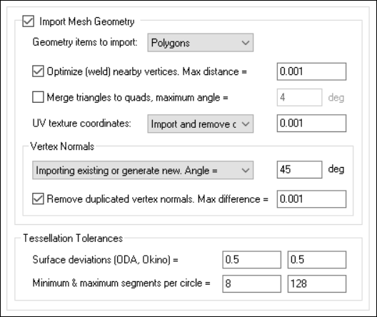
Import Mesh Geometry
This checkbox should not, in general, need to be disabled. It controls whether polygonal and poly-line data will be imported from the IFC file.Geometry items to import: Polygons, Line Segments, Polygons & Line Segments
IFC files contain geometric visualization entities which are either 3D polygonal meshes and/or 3D poly-lines. This combo box allows you to choose which are to be imported. By default only polygonal meshes are imported.Optimize (weld) nearby vertices. Max distance = ##
If this checkbox is enabled (check-marked) then the vertex welding operation will be applied to all polygon vertices once the IFC file has been read into memory and the objects created.Vertex welding collapses adjacent vertices which are within a distance less than or equal to the threshold value specified on the dialog box. Note that welding of vertices can only occur within a single object and not between different objects.
"Max distance" Type-In
If the distance between two vertices is less than or equal to this number, and the "Weld nearby vertices" checkbox is check-marked (enabled) then the two vertices will be collapsed (welded) into one.Merge triangles to quads, maximum angle = ##
This option is a post-processing step that merges triangles back to quadrilateral polygons (4 sided polygons). The number of vertices remain the same but the overall number of polygons are reduced.Note: MCAD files from programs such as SolidWorks, ProE/Creo, Autodesk Inventor, Unigraphics NX, Solid Edge and CATIA are almost always defined using triangle based geometry. However, since IFC files are primarily used for BIM and architectural construction, and in our experience, the polygonal mesh geometry is typically defined as quadrilateral polygonal meshes (“Quads”). As such, enabling this option may not do anything for the common IFC file given that their geometry is defined as quads already.
If this option is enabled (checkmarked) then an algorithm will be invoked which merges multiple polygons into quads. If two adjacent triangles are nearly co-planar then they will be turned into a quadrilateral. The vertices of the adjacent edges must be welded together (shared) for this operation to proceed properly.
The test for co-planar polygons (polygons which are almost on the same plane as each other) is determined by the "Max angle" type-in box. This value is measured in degrees. Values near 0 will require that adjacent polygons be very much co-planar with each other, while higher values will allow polygons that meet at an angle to be considered. For example, if you have a curved object made of triangles then try setting the angle to 4 to 7 degrees. Higher values will allow more polygons to be merged.
NOTE: you can also apply this merging algorithm via the "Polygon Processing" functionality found in the stand-alone Okino software. On that dialog box you would invoke the "Merge Co-Planar Polygons into larger polygons" function. That alternative version also provides some more controls over whether vertex normals, vertex colors and vertex uv’s are to be taken into account (they are all taken into account when invoked via the polygon reduction system).
UV texture coordinates:
As noted in the materials section, texture mapping has been poorly implemented in many IFC enabled applications over the last 3 decades. Regardless, Okino has implemented texture mapping in this IFC importer.If and when available, the UV texture coordinates will be imported along with the 3D polygonal mesh geometry. Please note that MCAD geometric entities defined in the IFC file such as BREP solids and NURBS surfaces will naturally not have any UV texture coordinates assigned to them.
Do not import
If this combo box option is chosen then no UV texture coordinates will be imported.Import as-is
If this combo box option is chosen then the raw UV texture coordinates will be imported as-is.Import and remove duplicated coordinates
If this combo box option is chosen then the raw UV texture coordinates will be imported and then any replicated coordinates removed based on the maximum difference between them defined by the type-in value. This value is in the “coordinate system of the UV texture values” or “UV space”.Vertex Normals
Vertex normals are 3D vectors which point away from the vertices of each polygonal mesh object. These vectors help a destination 3D program render an otherwise faceted mesh object as smooth. It is these vertex normals which can make a faceted sphere render as looking entirely smooth. If a model does not have any vertex normals then the geometry will look all faceted and not smooth.Since the early to mid 1990s almost all source 3D models have had vertex normals associated with their polygonal mesh data (except for 1980’s file formats such as STL, DXF/DWG and .3ds). However, oddly, IFC files disdain the usage of vertex normals with their tessellated mesh geometry – that makes sense as many IFC models are quite angular in their nature (ie. walls, floors, roofs, I-breams, etc).
The following options aid with the import of the vertex normals and/or the automatic computation of new vertex normals for a geometry item.
Combo box operation:
Do not import
If this combo box option is chosen then no vertex normal coordinates will be imported.Import existing values
If this combo box option is chosen then any existing vertex normal coordinates defined within the IFC file will be imported as-is.Generate new values = ##
If this combo box option is chosen then brand new vertex normals will be computed for a mesh model. This will be purely a “best guess” approximation based on how smooth the geometry is.The smoothing criterion is based on the angle between abutting polygons; common smoothed vertex normals will be computed if the angle between their geometric surfaces normals is less than the angle specified on the dialog box (which defaults to 45 degrees).
In general you will want to use a smoothing angle of (roughly) 15 degrees to 60 degrees. However, 45 degrees is a safe bet.
Import existing or generate new values = ##
This combo box option is similar to the last two combined together.If the imported polygonal mesh data has existing, explicit vertex normals then they will be used as-is. However, if the mesh data has no existing explicit vertex normals then new ones will be computed in the manner explained in the “Generate new values” section.
Remove duplicated vertex normals. Max difference = ##
This is the same as the 'Optimize (weld) nearby vertices' function except that it combines redundant vertex normals that are within a certain numerical threshold of each other.Tessellation Tolerances
These are presently experimental features of the IFC importer and are exposed for value testing and tweaking.Statistically speaking, from our own experience, IFC files have their 3D objects pre-tessellated into quad-based, polygonal mesh models. However, since IFC is based on the STEP file format, an IFC file can also contain BREP solids and NURBS based procedural 3D geometry items.
When a BREP or NURBS surface is imported it must be tessellated into a polygonal mesh. The number of subdivisions of the procedural geometry into a polygonal object is defined by these type-in numbers. In theory, the lower these numbers the higher the number of polygons are generated (and thus a smoother, less faceted surface).
Surface deviations (ODA, Okino) = 0.5, 0.5
These values determine how smooth the tessellated BREP solids and/or NURBS surfaces will be once that they are turned into a polygonal mesh. Smaller values will create larger number of polygons and hence a finer quality mesh.Minimum & maximum segments per circle = 8, 128
These values control how fine a circle will be tessellated during import. In most cases these values, and such a tessellation procedure, will never be used during an IFC file importer. As such, this is an experimental feature.
This panel controls which form of scene & instance-node optimizations will be performed on the import IFC data.
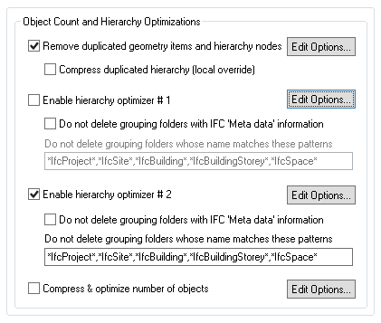
Remove duplicated geometry items and hierarchy nodes
This option is enabled by default as it will locate and find duplicated items within an imported IFC scene. For example, if the optimizer locates 1000 copies of the same IfcBeam or IfcColumn entity then it’ll replace those explicit copies with a single geometry definition pointed to by 1000 reference (“1000 instances of a single Okino master object geometry definition”).Note that this optimizer is equivalent to running the “Remove duplicated geometry/hierarchy via re-instancing algorithm” command from within the Okino stand-alone software, from the “Win” menu of the upper-right Selector Window.
There is extensive online help for this command by pressing the “Edit Options…” button and then the Help button on the dialog box which appears.
Compress duplicated hierarchy (local override)
In general this checkbox should be disabled (uncheckmarked) for perceptual reasons, as will be explained herein. If you want the most optimal of imported IFC files then go and enable it.This checkbox is a 100% local override to the exact same-named option found on the optimizer’s “Edit Options…” dialog box. In other words, the state of this local checkbox entirely overrides the one shown on the optimizer’s dialog box.
This is the only usage of a “local override” in all of Okino software. Why was it created? Because of perceptual reasons. Logically and in theory this checkbox should be enabled to get the most optimal of imported IFC files. However, in some cases it will introduce “Okino red folders” into the imported node hierarchy which are correct and necessary for optimization reasons. But people who often deal with IFC files and their hierarchical naming may find the usage of these Okino red folders to be irksome or odd in nature. However, if you are a common user of our MCAD importers (STEP, IGES, ProE/Creo, etc) then you will find that these “red folders” are a fundamental aspect of the imported MCAD data.
Enable hierarchy optimizer # 1, Enable hierarchy optimizer # 2
These options provide methods to remove redundant hierarchy nodes ("NULLs", or grouping folders) from the imported file.
- Optimizer #1 removes runs of empty folders, as well as folders with no children. This is disabled by default.
- Optimizer #2 is simpler, deleting empty folders which only have 1 geometry object in them. This is enabled by default.
These options can also be enabled via the "Optimize hierarchy after completion" checkbox found on the options dialog box of the "Compress & optimize number of objects" option (see below).
Do not delete grouping folders with IFC 'Meta data' information
IFC grouping folders and geometry nodes most often contain a LOT of meta data information (which is imported along with the node from the IFC file itself).By default (when this checkbox is disabled), the optimizer will be allowed to delete such redundant grouping folder nodes, regardless of whether there is any meta data information on them or not.
However, if this checkbox is enabled then the redundant grouping folder will not be allowed to be deleted by the optimizer if it is found that there is meta data information on it.
The choice of whether to allow such redundant grouping folders to be deleted is up to yourself and whether you need access to every imported node of the IFC file which has had valid meta data information associated with them.
Note: this local IFC-centric checkbox completely overrides the corresponding checkbox (“Meta data associated with it”) found on the optimizer’s main options dialog box (which is accessible via the “Edit Options….” button).
Do not delete grouping folders whose name matches these patterns
There may be cases when you may not want specific grouping folders to be deleted during the optimization process.For example, a person who is familiar with IFC files will probably not want any of the “IFC Spatial” nodes to be deleted even if they are not important at all to the imported 3D scene. The following is a visual snapshot of such spatial “grouping folders”:

This text type-in box contains a list of pattern matching strings. If any grouping folder’s name matches one or more of these pattern matching strings then that folder will not be deleted.
Each pattern matching string is separated from the next one by a comma.
The default list of strings is:
*IfcProject*,*IfcSite*,*IfcBuilding*,*IfcBuildingStorey*,*IfcSpace*
Note: this list of strings supplements/appends-to (and does not override) the list of pattern matching strings found on the optimizer’s options dialog box.
The syntax of the pattern matching string is defined as follows:
- 1. * matches any sequence of zero or more characters,
- 2. ? matches any single character,
- 3. [SET] matches any single character specified by the SET, where any other character other than the minus sign or the close bracket may appear in the set. A set is composed of characters or ranges; a range is indicated by two characters separated by a minus sign, such as in 0-9 or A-Z.
[0-9a-zA-Z_] is the minimal set of characters allowed in the [SET] pattern construct. Other characters are allowed (ie. 8 bit characters) if your system will support them.
[!SET] or [^SET] matches any character not in the specified set.
- 4. To suppress the special syntactic significance of any of '[]*?!^-\', and match the character exactly, precede it with a '\'.
The following are example pattern matching strings:
*		Matches everything
?		Matches all one character strings
???		Matches all three character strings
*test		Matches '1test', 'thisisatest', 'test'
t*s*t		Matches 'test', 'tesseract'
[a-z]s*t		Matches 'asset'
s[!gh]t		Matches 'set'
s[!e]t		Doesn't match 'set'
[a-fh-z]*		Matches 'jack', 'flack', 'zoom'
i\**		Matches 'i*guess'
[\[-\]]		Matches '[' and ']'
[a-z\\]		Matches a, b, c, \
Compress & optimize number of objects
This checkbox enables one of the most important and critical scene processing functions in all of Okino software. It is an integral and core part of any Okino CAD importer, and it has been added to the IFC importer for added benefits.Note: Unlike all other Okino 3D importers, this optimizer is turned off by default. The primary reason is that many people importing IFC files will most likely wish to see all of the explicit components in the imported hierarchy (such as all of the beams, columns, roofs, walls, buildings, etc). On the other hand, animators who import from MCAD programs (such as SolidWorks and Unigraphics) want the most optimal and highest efficiency imported model, which means that much of the imported geometry and node hierarchy be compressed up as much as possible.
The primary purpose of this function is to walk the imported geometry hierarchy and compress together all objects that are parented under a single folder into a one new object. For example, if you import a IFC file and find that 200 polygonal objects are grouped under one folder, then enabling this option will cause all such occurrences to collapse the children geometry of each grouping folder into one object.
Note that this optimizer is equivalent to running the “Optimize Scene – Number of Objects & Folders” command from within the Okino stand-alone software, from the “Win” menu of the upper-right Selector Window.
The documentation for this option can be viewed by pressing the "Edit Options…" button and then the "Help" button on the optimizer's dialog box.
This panel controls (1) units matching, (2) automatic center re-centering, (3) scene scaling and (4) some miscellaneous options.
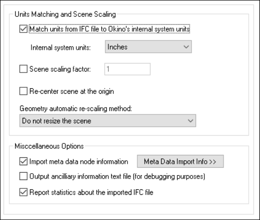
Units Matching and Scene Scaling
Match units from IFC file to Okino's internal system units
CAD files most often have an associated “unit of measure” such as meters, feet, inches, etc. Thus, a raw value of “1.0” can then be considered and tagged as “1.0 meters”However, when these models are imported into another 3D package that uses a different unit of measure then a "units conversion" needs to occur. For example, Maya uses cm, 3ds Max and SketchUp use inches by default, LightWave uses cm or meters, MicroStation uses mm, etc. This happens by applying an internally computed scale factor to all of the imported 3D coordinates data.
If this checkbox is enabled then the IFC importer will rescale all imported geometry so that the units of the IFC file can be made to match the units of the current internal Okino database. If the checkbox is disabled then the geometry will be imported unchanged and untouched, meaning that its scale may be "incorrect".
Internal System Units
This drop-down combo box specifies the current units system in effect within the internal Okino 3D database. It defaults to meters. What you need to do is select an appropriate entry from the drop-down combo box which matches the system units used by your destination program: for example, set it to Centimeters for Lightwave, Inches for 3ds Max, Centimeters for Maya, etc.
None No units; never do any geometry scaling Custom Custom units are in effect. See below Microinches 1e-6 inches Mils 1e-3 inches Inches 0.0254 meters Feet 12 inches Miles 63360 inches Microns 1e-6 meters Millimeters 1e-3 meters Centimeters 1e-2 meters Meters Kilometers 1e+3 meters Scene scaling factor - ##
This value allows a custom scaling to be applied to the overall imported scene.For example, if set to 10.0 then the imported scene will be scaled 10 times larger. If set to 0.1 then the imported scene will be scaled 10 times smaller.
Re-center scene at the origin
If this checkbox is enabled then the scene will be re-centered at the origin, based on the overall bounding box of the imported scene.It is common for architectural models to be geo-located and hence end up being hundreds of thousands to billions of units away from the origin. Why is this bad? Well, very few or no 3D users are aware of our common daily explanation. Many source MCAD modelers using double precision floating point numbers which have 16 digits of very high precision. However, almost all downstream programs that you’ll take your IFC files into only use single precision floating point numbers with a lowly 6 digits of numerical precision. What that means is that these destination programs do not have the numerical fidelity to encode a number such as “1,000,000.1234” as the .1234 portion will be chopped off. We have seen MANY cases of an AutoCAD user placing a house (which is only 0.1 units across) many millions to billions of units away from the origin, then wondering why their model implodes to a dot when converted to a non-MCAD program.
As such, this option brings the model back to the origin where it should retain more numerical precision.
Geometry Automatic Rescaling Method
This combo box provides access to a useful mechanism which automatically rescales the imported mesh geometry to a size best needed by other 3D software packages. This combo box can be used to automatically resize any imported model data to a useful size, such as scaled to easily fit inside a box of 2x2x2 raw working units (which is the default). The various options are described as follows:Do Not Resize the Scene
No resizing is done to the imported data.Resize to 1x1x1 units
Resize to 2x2x2 units>
The model data is automatically scaled up in size, or scaled down in size so that its worldspace extents fits inside a 1x1x1 or 2x2x2 sized unit cube. The latter is the default.Resize to User Defined Absolute Size
The model data is automatically scaled up in size, or scaled down in size so that its worldspace extents fit inside a cube whose size is user defined by the type-in value shown on the dialog box. For example, if you enter the value 20 then the imported data will be resized so that its maximum extent in one or more dimensions is 20 units.Scale Larger by User Defined Factor
Scale Smaller by User Defined Factor
These options allow the imported model data to be scaled larger or scaled smaller by an absolute number. For example, if you select the ‘larger’ option and enter 10 into the type-in box, then the imported model will be scaled 10 times larger during the import process.Miscellaneous Options
Import meta data node information
A key aspect of the IFC file format is the “meta data” (properties) associated with each node in the file.If this checkbox is checkmarked then meta data will be imported from the IfcProject node, the IFC file’s header and each child node.
The meta data from the IfcProject node and file’s header will be imported into the Okino scene graph as “global scene meta data”. This information is accessible within the stand-alone Okino software via the “Edit / Preferences / Global scene meta data” dialog box. Otherwise, the node-based meta data will be assigned to Okino “instance definitions” – such meta data can be viewed within the stand-alone Okino software via the “Meta Data” tool window (located in the lower right corner of the UI) and via the “Meta Data” panel of the Instance Attributes editor (which is accessible by right clicking on an Instance name in the upper-right Selector Window and choosing the ‘Edit instance attributes’ menu item).
NOTE:
If you wish to import meta data while the 'Compress and optimize number of objects' checkbox is enabled on the 'Optimizations' panel, you will need to change the following importer processing option so that certain “redundant” instance nodes will not be unnecessarily deleted:
- Press the 'Edit Options...' button located to the right of the 'Compress and optimize number of objects' checkbox on the 'Optimizations' panel.
- Press the 'Hierarchy Options...' button located to the right of the 'Optimize hierarchy after completion' checkbox.
- Enable the checkbox for 'Meta data associated with it' on the 'Folder Hierarchy Optimizer' options dialog box."
The meta data imported from the IfcProject node and file’s header will also be displayed after import of the IFC file if and when the “Report statistics about the imported IFC file” checkbox is enabled:
IfcProject and file header meta data:
Project Name = Vectorworks Project
Owner info, person's name =  Architect
Owner info, organization's name =  Nemetschek Vectorworks
Owning application, developer's name =  Nemetschek Vectorworks
Owning application, full name = Vectorworks Architect
Owning application, identifier = VW1803
Owning application, version = 18_0_3_1
Description #1 = ViewDefinition [CoordinationView_V2.0]
Description #2 = ExchangeRequirement[Architecture]
Implementation Level = 2;1
Time Stamp = 2013-04-19T12:40:00
Preprocessor Version = Vectorworks Architect
Originating System = Macintosh
Author = Architect
Organization = Nemetschek Vectorworks, Inc.
Output ancillary information text file (for debugging purposes)
If this checkbox is checkmarked then additional verbose information about the source IFC file will be saved to a text file located in the directory from where the IFC file was loaded. The file will have “- Info.txt” appended to the original IFC filename. In general you will not need to look at this file.Specifically, the file will contain information about each IFC entity imported from the IFC file, the node hierarchy of the entities, a list of IfcMaterials found in the file, the IfcProject & header meta data, and of the progress made during the vectorization process of each geometric entity.
Entity 15731:
Entity handle (corresponds to the STEP-id) = 15731
Entity type code = 649
Entity type name = 'IfcPresentationLayerAssignment'
Entity is kind of kBIM

IfcMaterial = STEEL/A36, object_id # 1 = 51
IfcMaterial = STEEL/A36, object_id # 3 = 145

Level 0 - 'IfcProject', Unique ID = 25. Type = Entity
	Level 1 - 'Undefined', Unique ID = 27. Type = Entity
		Level 2 - 'Undefined', Unique ID = 29. Type = Entity
			Level 3 - '+0', Unique ID = 14731. Type = Entity
			Level 3 - '+18'-1', Unique ID = 14744. Type = Entity
			Level 3 - 'Undefined', Unique ID = 31. Type = Entity
				Level 4 - 'CHANNEL', Unique ID = 51. Type = Entity

Starting vectorization of 'IfcBeam / CHANNEL / C12X20.7'
        In draw() function. ShapeRepresentation Id = 48
                0.000000 -1.000000 0.000000 0.000000
                1.000000 0.000000 0.000000 0.000000
                0.000000 0.000000 1.000000 0.000000
                -1562.100000 4260.850595 5359.400000 1.000000
        In doDraw() function -- isPersistent() = 1
        In onTraitsModified() function
                Geometric Id = 47, surface name = STEEL/A36
                Colour - 229, 0, 0
        In shellProc() function
Ending vectorization of 'IfcBeam / CHANNEL / C12X20.7'
Report statistics about the imported IFC file
If this checkbox is checkmarked then statistics will be output after the IFC file has been imported, which looks like this:IFC file parsing statistics: Mesh Totals: Polygons = 768333 Vertex coordinates = 746058 Vertex indices = 2967921 Objects = 6462 Materials = 52 Texture definitions = 1 Meta data (scene level) = 14 Meta data (node level) = 210154 Time elapsed (min:sec): 00:33Also, a roll-up of the scene-level meta data extracted from the IFC file’s header will be displayed if the “Import meta data node information” is enabled on this same panel.
This panel controls the processing and optimization of IFC “Styles” which are otherwise known as “Materials” and “Surfaces” in other 3D programs. As noted further below, please do not confuse IfcStyles with IfcMaterials.
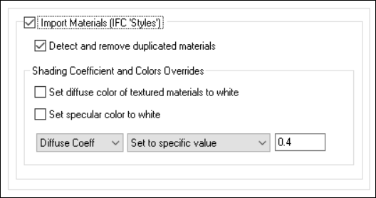
Notes:
- For many decades the IFC file format specification has caused untold confusion and disappointment when it comes to traditional “visual/rendered material attributes and assignment” support. IFC is severely lacking in this area of its specification.
- In very basic terms, RGB colors are defined via a “IfcStyle” and its associated “IfcSurfaceStyle”. A geometric entity make reference to such IfcStyles in order to have colors associated with them. These colors are used during the visualization process.
- Confusion comes about from the mention of “IfcMaterials”. These are not traditional rendering materials as are otherwise used in DCC/Animation and MCAD programs. Rather, an IfcMaterial defines real world material properties such as concrete strength, thermal properties, mechanical properties or a custom property defined by the user. Some IFC4 or newer files may have the geometric entity refer to an IfcMaterial and then have the IfcMaterial make reference to a IfcStyle to define the RGB colors of the geometry.
- This importer has a complex mechanism to decide if and where the RGB color(s) will be extracted for a geometric entity, either from the IfcStyle/IfcSurfaceStyle pair or indirectly via an assigned IfcMaterial. These visual attributes will be accumulated into a unique Okino-style “Surface” (material) definition.
- 2D bitmap image texture mapping is terribly under-supported in the IFC file format specification. The maintainers of the file format have shown little interest in formally supporting and pushing texture mapping over the prior 3 decades. If you want to convert texture mapped architectural models then that should ideally be done with Okino’s DWF-3D conversion system.
Import Materials (IFC 'Styles')
If this checkbox is checkmarked then visual/rendering attributes of each geometric entity will be imported as Okino surface (material) definitions, as noted in the above explanations.The visual attributes will be extracted from IfcStyles found in the file. In particular, from the IfcSurfaceStyle child entity type. Of this, 4 child surface style types are supported:
IfcSurfaceStyleLighting
IfcSurfaceStyleRefraction
IfcSurfaceStyleShading
IfcSurfaceStyleWithTextures
From those 4 listed above, the following rendering attributes will be extracted and mapped over to Okino surface/material definitions:
Diffuse Colour
Reflection Colour
Specular Colour
Transparency
Specular Highlight
Specular Exponent
Specular Roughness
Reflectance Method (Phong or Blinn)
Refraction Index
As explained further above, bitmap texture mapping capabilities are poorly supported in most IFC exporters and downstream IFC importers + file viewers. There just seems to be little interest or focus on texture mapping within IFC enabled applications. Nevertheless, Okino pioneered texture mapping conversion over its prior 30+ years and hence has very good parsing and import support for texture mapping via the IfcSurfaceStyleWithTextures entity type and its associated child IfcSurfaceTexture entity type.
From IfcSurfaceTexture:
RepeatS, RepeatT TextureType (TEXTURE, BUMP, OPACITY, etc) TextureTransform & IfcCartesianTransformationOperator2DFrom TextureType: IfcImageTexture, IfcPixelTexture and IfcBlobTexture are supported.
From IfcImageTexture: UrlReference
The URL reference will be imported as a file-relative path & filename to an existing bitmap texture image located on the local disk.From IfcPixelTexture: Width, Height, ColourComponents and Pixel
PixelTextures will be extracted from the IFC file and saved to disk as TIFF files.From IfcBlobTexture: RasterFormat (BMP, JPG, PNG, GIF) and RasterCode
BlobTextures will be extracted from the IFC file and saved to disk in their original bitmap file format as defined by the IFC file.And the following TextureType enums are supported: Texture, Bump, Opacity, Reflection, Self Illumination, Shininess, Specular and Transparency mapping.
Detect and remove duplicated materials
If this checkbox is checkmarked then only unique material (surface) definitions will be created. The uniqueness will be achieved by comparing all imported visual attributes and texture maps attributes.Set diffuse color of textured materials to white
This is one of those options that may come in handy for someone with particular requirements for their textured objects in the IFC file.If this checkbox is checkmarked then any material which has a diffuse texture map assigned to it will be output in such a way that its diffuse surface color will be set to white.
This is useful because certain real-time renderers use an "OpenGL" shading model in which the diffuse color is multiplied into the assigned texture map colors - if the diffuse material color is dark or black then the texture map will not be visible (often a problem when exporting from Maya for which the diffuse surface color is always set to black for textured materials). Enabling this option will cause the diffuse surface color to become white, and thus it will not affect the brightness of the assigned texture map.
If this checkbox is not checkmarked then the diffuse surface color will be imported unchanged.
This option can be enabled in case texture maps look too bright or washed after being imported from the IFC file.
Set specular color to white
If this checkbox is enabled then the specular material color will always be set to white (although, the white can be dimmed by changing the 'Specular Coefficient' material parameter override, as described above). If disabled, then the real material's specular color will be imported.Shading Coefficient and Colors Overrides
These combo box options allow the various imported material attributes to be fine tuned or outright modified. The two combo boxes and the single numeric text box provide good control over the ambient, diffuse, specular, opacity and shininess shading coefficients imported from the IFC file.Note: IFC revolves around an “OpenGL-like” shading model for which the diffuse and specular colors will be 100% saturated. When imported and rendered in a visualization program (such as Autodesk Maya, Autodesk 3ds Max, etc.) they will look washed out and super-saturated. As such, these combo boxes are preset to set the diffuse to 40% and specular to 70% of their imported colors; by doing so the imported IFC model should be in a “load and render” state.
The first drop-down combo box selects which of these shading parameters is to be modified. Each shading coefficient has its own operation that can be selected (via the second combo box) and an optional numeric text value (via the third data entry text input box). The following describes the various shading parameters that can be controlled:
- Diffuse Coefficient: This controls the amount of color reflected from an object based on the direct light shining on it. A good default value is 0.4 and ideally ranges from 0.0 to 1.0.
- Specular Coefficient: This controls the intensity of the highlight color on an object. A good default value is 0.7 and ideally ranges from 0.0 to 5.0.
- Opacity: This is the inverse of transparency. 0.0 will make the object fully transparent, while at 1.0 the object will be fully opaque.
- Phong Shininess: This controls the width of the specular highlight seen on an object. An ideal range is 6 (very wide) to 300 (very narrow). The default is 32.
For each material shading parameter, several actions can be performed on each material shading parameter during the import process:
- Do Not Import: The shading parameter is not imported at all. No value is imported nor sent to the Okino software. Thus, the default material shading parameter value (as set inside Okino software) will be used instead.
- Import Unchanged: The shading parameter is imported as is, with no change.
- Set and Use Default: The shading parameter is set to some "good" default value (as determined by the import converter). This default value will be shown in the type-in box.
- Set to Specific Value: The imported shading parameter will be overridden with the user specified value of the numeric type-in box.
- Import and Crop by: The shading parameter is imported and will remain unchanged if it is less than the numeric type-in value shown on the dialog box. If it is greater, then the imported value will be clamped to be no greater than the numeric type-in value. This is a good operation, for example, if you do not wish for the ambient shading coefficient to be greater than 0.3.
- Import and Scale by: The shading parameter is imported and multiplied by the numeric type-in value shown on the dialog box
This panel controls how embedded bitmap texture images are extracted from an IFC file.
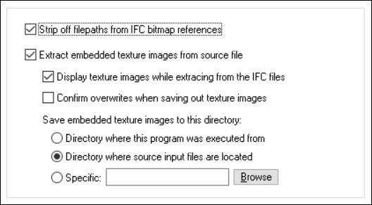
Strip off filepaths from IFC bitmap reference
An “IfcImageTexture” provides a Url Reference to a bitmap texture image. If this checkbox is checkmarked then any prefix or file path will be stripped off of the bitmap filename itself. It is enabled by default.Extract embedded texture images from source file
IFC allows for bitmap texture images to be embedded within a file.If this checkbox is checkmarked then IfcPixelTexture and IfcBlobTexture embedded images will be extracted and saved to disk. Those defined in a IfcPixelTexture will be saved to a TIFF file while those defined in a IfcBlobTexture will be extracted directly to an equivalent BMP, JPG, PNG or GIF file.
Display texture images while extracting from the IFC files
If this checkbox is checkmarked then IfcPixelTexture embedded images will be displayed as they are being processed.Confirm overwrites when saving out texture images
If this checkbox is checkmarked then you will be prompted if an existing bitmap image on disk is about to be overwritten. However, that should never occur as the IFC bitmap extractor will always create unique filenames.Save embedded texture images to this directory:
These radio buttons determine where the extracted bitmap images will be saved to.Directory where this program was executed from
This option will save the bitmap images to the same directory from where the Okino software was executed from.Directory where source input files are located
This option will save the bitmap images to the directory from where the IFC file was loaded from.Specific
This option will save the bitmap images to the user specified directory. Press the “Browse” button to select a new directory location.

