| You are here: Home » Import CAD Formats » NGRAIN's 3KO Solutions |
|
The Wavefront OBJ geometry export converter writes out the scene database as indexed polygon meshes (faces and their associated indices), 3D linesets and 3D point sets, along with optional normal and texture data (if its exists within the database). A Wavefront material definition file (.mtl) can also be exported which supports all material and texture options (ie: Ka, Ks, Kd, map_Ka, map_Kd, map_Ks, map_Bump, etc). The export converter also features extensive automatic 2d bitmap conversion options and features (see dialog box description below).
Please also refer to the corresponding Wavefront import converter.
The Wavefront file format is quite robust and is a popular format used to transfer entire object geometries between 3D packages.
Polygons that belong to the same object within the converter's internal database will output as a single unique group within the .OBJ file with the group's name set equal to the internal object name; the group name is specified with the "g" command in the file.
No hierarchy information is output since the .OBJ file format has no methods to describing hierarchy; each sub-object of a hierarchy will nonetheless be exported as a unique group whose name's match the original object names in the internal database hierarchy.

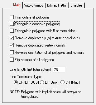
The following information explains the various options on the dialog box:
Triangulate Concave Polygons
If this option is enabled (checkmarked) then all 4-sided or greater polygons which are concave will be triangulated prior to being output to the OBJ file.Triangulate Polygons with 5 or More Sides
If this option is enabled (checkmarked) then polygons with 5 or more sides (polygons which are not triangles or quads) will be triangulated prior to being output to the OBJ file.Remove Duplicated (u,v) Texture Coordinates
If this option is enabled (checkmarked) an optimization algorithm will be invoked to remove any duplicated (u,v) texture coordinates from the exported mesh data.Remove Duplicated Vertex Normals
If this option is enabled (checkmarked) an optimization algorithm will be invoked to remove any duplicated vertex normals from the exported mesh data.Reverse orientation of all polygons and normals
If this option is enabled (checkmarked) then the orientation of all polygons will be reversed (this will effectively swap the orientation of the polygons' geometric normals).Flip normals of all polygons
If this option is enabled (checkmarked) then the vertex normals of each polygon will be flipped.Line Length Limit (characters)
This type-in value determines the maximum length of each line exported to the Wavefront geometry file. The default is 78 characters.

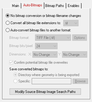
This dialog box allows referenced bitmaps (of the internal 3D scene database) to be automatically converted to other 2d bitmap formats during the export process. The three options available are:
- Do not modify the bitmap filename reference and do not perform any bitmap conversion.
- Modify the extension of the bitmap filename to a bitmap format (chosen from a drop-down list) but do not perform any bitmap conversion. This option is useful if you have (1) either performed the bitmap conversions in a previous export process or (2) you wish to use an external program (such as PhotoShop) to perform the bitmap conversions.
- Perform bitmap conversion and change the file extension of the bitmap. For example, if your original 3D scene data referenced JPEG bitmaps, but you want the exported Wavefront file to reference BMP bitmaps, then this option can be used to automatically convert the JPEG files to BMP and change all bitmap references to the new BMP files.
No Bitmap Conversion or Bitmap Filename Changes (Radio Button)
If this radio button is chosen then any bitmap reference exported into the Wavefront file will not be changed, its filename extension won't be changed, the path to the bitmap will not be changed and no bitmap conversion will be done.Convert all Bitmap File References To... (Radio Button)
Rather than convert referenced bitmap images to another file format this radio button (when selected) simply changes all the file extensions on bitmap files to a specific type. For example, if set to "TIFF" then all bitmap filenames exported to the Wavefront file will be changed so that their file extensions end in ".tif". This is a useful option is you already have all of the referenced texture maps converted to the desired file format (either from a previous invocation of this export converter or by using a batch bitmap conversion program).Auto-Convert Bitmap Files to Another Format (Radio Button)
If this radio button is selected then all 2d bitmap textures which are currently defined and referenced by the internal NuGraf/PolyTrans database scene will be automatically tagged then converted to a new user-specified 2d bitmap file format during export. The desired format is chosen using the Bitmap File Format combo box. If the texture(s) cannot be found in the location specified by the pathname prepended to the input texture filename then the export converter will search for the texture(s) in all directories specified in the 'Default Search Path' and the 'Texture Bitmaps Search Path' file search paths (these can be modified by choosing the 'Preferences/Configure File Search Paths' menu item.Bitmap File Format (Combo Box)
This combo box lists the destination bitmap file format.Bitmap Depth (Bits/Pixel): 2, 4, 8, 24
These radio buttons determine the number of bits/pixel to write out to the new 2d bitmap file. The default is 24 bits. A color quantization algorithm will be used for the 2, 4 and 8 bits/pixel output formats.Dimensions: X = #, Y = #
These two drop-down list boxes determine the X and Y resolution for the converted bitmap file(s):
No Change = Do not change the X or Y size Closest = Use the next highest power-of-2 size 2, 4, 8, ... 256, 512 = Choose a specific size for the X or Y dimension Confirm Potential Bitmap File Overwrites
If this checkbox is enabled (checkmarked) then the bitmap converter will confirm any potential overwrites of existing bitmap files on disk which have the same filename and extension as the one being written. If this option is disabled then no confirmation will be made.Save Converted Bitmaps To...
These radio buttons determine where the new bitmap file will be written to. Note that enabling the 'Replace all Bitmap File Paths With This Path:' option or the 'Strip File Paths From All Bitmap References' option below will change the path prefix for the converted bitmap even though it was saved to disk in the location specified by one of these 2 radio buttons.Directory Where Geometry Is Being Exported
The new bitmaps will be written to the directory where the Wavefront file is being exported to.Specific + Browse
The new bitmaps will be written to the directory specified by the text box. This directory can be changed by press the 'Browse' button.

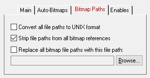
Convert all file paths to UNIX format
If this option is enabled (checkmarked) then all bitmap file paths written to the Wavefront file will be converted to a UNIX compatible format. In particular, all DOS-specific backward slashes '\' will be converted to UNIX forward slash '/' directory separators. Also, any DOS-like drive specifiers, such as "c:\" will be removed from the file path and a warning message will be reported about the removal of this drive specifier (you should make sure that all DOS-like drive specifiers be replaced by UNC specifiers, such as \\machine1\). If this option is disabled then no conversions will be made.Strip File Paths From All Bitmap References
If this checkbox is check-marked then all bitmap file references will have their filename path removed from them prior to export to the Wavefront material file. If this option is disabled then the filepath and filename to the bitmap reference will not be changed.Use Absolute Paths for all bitmap file references
If this checkbox is check-marked then all bitmap files which are stored as references in the Wavefront material file will have an absolute filepath prefixed to them. This option should only be enabled if the location of the bitmap files is not to change after the conversion process is done. If this option is disabled then the bitmap references will be output with no changes at all; such references may or may not have absolute file paths on them.Replace all Bitmap File Paths With This Path
This option allows all bitmap references exported to the Wavefront material file to be prefixed with a new filepath. This might be useful, for example, if all of your bitmap files are located in one specific directory or if you wish to change the prefix on the imported bitmap references. This new path will override all other options on this bitmap conversion dialog box (in other words, it will replace a bitmap's file path regardless of any other file path added to the bitmap via other options in this dialog box). To choose the filepath press the "Browse" button. To disable this option, click on the checkbox again so that it comes un-checkmarked.

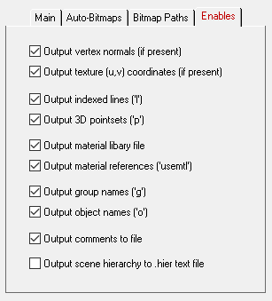
Output Vertex Normals (If Present)
If this option is enabled (checkmarked) then vertex normals will be output to the OBJ file along with the vertex data.Output Texture (u,v) Coordinates (If Present)
If this option is enabled (checkmarked) then texture (u,v) coordinates will be output to the OBJ file along with the vertex data.Output Indexed Lines ("l")
If this option is enabled (checkmarked) then any internal database "indexed polyline" primitives will be output to the Wavefront OBJ file as "l" line primitives. This differs from polygon data in that the lines have no area and do not have to be closed.Output 3D Pointsets ("p")
If this option is enabled (checkmarked) then any internal database "3d Pointset" primitives will be output to the Wavefront OBJ file as "p" point primitives. A point primitive in an OBJ file can have 1 or more vertices.Output Material Library File
If this option is enabled (checkmarked) then a Wavefront compatible material file will be output along with the main .obj geometry file. This file will have the same root filename as the input filename but with a .mtl file extension (ie.: input = filename.3ds, output = filename.obj and filename.mtl). The material file will list all of the material definitions referenced by the geometry as well as specify some of the material properties such as Ns, Ka, Kd, Ks and the shading model (see below for their explanations). Note that the Wavefront material file does not accommodate texture filename information. If this option is disabled (uncheckmarked) then no material file will be output.Output Material References ('usemtl')
If this option is enabled (checkmarked) then 'usemtl' statements will be output to the Wavefront .obj geometry file. These statements link a material definition to the polygon(s) which follow it. The material definition name corresponds to the materials output to the material library file (see above).Output Group Names ('g')
If this option is enabled (checkmarked) then a group name will preceed each collection of polygons ('g name'). The group name will be equivalent to name assigned to the object.Output Object Names ('o')
If this option is enabled (checkmarked) then an object name will preceed each collection of polygons ('o name'). This name is the same as that output for the 'g' command outlined above. Only programs such as SoftImage, Wavefront, NuGraf and PolyTrans actually do anything with this 'o' command.Output Comments to File
If this option is enabled (checkmarked) then comments will be output to the Wavefront geometry and material files. If this option is disabled then no comments will be output.Output Scene Hierarchy to '.hier' Text File
For historical reasons the Wavefront OBJ file format has no context for hierarchy information. Hierarchy defines the "parent/child relationship" amongst instances of object definitions within a scene. To overcome this limitation a special ".hier" file can be optionally output along with the main Wavefront OBJ file. The .hier file is a custom text file written out from the Okino 3D scene database based on Okino's own pre-defined syntax. This .hier file can be parsed by destination programs which have been written to recogonize and import this Okino .hier file.Enabling this checkbox will cause the object hierarchy to be output to a separate text file with the extension ".hier" and the root name of the exported Wavefront OBJ file.
Syntax Of the .hier File
{ = This line defines a new hierarchy level using an Okino NULL node, "empty instance" or "grouping folder" (all of which are the same in Okino lingo). It will have 0 or more children instances. The hierarchy level ends with the matching "}" closing bracket.
[ ] = Denotes a geometry instance item. Each such line contains a single instance of an Okino object definition such as a mesh item, point cloud item or curve item. The hierarchy level does not increase or decrease.
In order for a destination program to best reconstruct the localized child/parent hierarchy, each line of the .hier file contains the following information. Keep in mind that the OBJ file's data is entirely flattened into world-space coordinates with no usage of instancing to remove any duplicate geometry items (those are limitations of using the OBJ file format).
orig_inst_name = This is the original instance name as defined within the original Okino 3D scene database prior to export.
uniq_inst_name = This is the orig_inst_name name but after it has been made unique within the context of the OBJ file. For example, there may be an instance called "screw" in the Okino 3D database but due to instancing it may create 3 copies in the OBJ file for which the names stored within the file would be "screw", "screw1" and "screw2".
node_id = This is a unique ID # which is assigned to each line within the .hier file. You will also find a corresponding ID # within the Wavefront OBJ file within a comment line. This will allow you to match up the actual geometry object definition within the OBJ file to its corresponding line in the .hier file.
local_transform = The local 4x4 transformation matrix associated with the original instance within the Okino scene database. This matrix is relative to its direct parent.
global_transform = The global 4x4 transformation matrix associated with the original instance within the Okino scene database. This matrix takes the original instance and transforms it into world-space coordinates.
Notes:
- Always keep in mind that Wavefront OBJ files have been 'flattened' and have no instancing capability. Hence, if there are 3 copies of a screw then the OBJ file will have 3 explicit geometry copies within the OBJ file. Using the .hier file you can determine which items were instanced.
The following is an example .hier text file of the "colacans.bdf" file. Each indentation indicates the start of a new grouping folder (or hierarchy level).
{ uniq_inst_name="world", orig_inst_name="world", node_id="0"
{ uniq_inst_name="can1", orig_inst_name="can1", node_id="1", local_transform="0.0385195 0 -0.297517 0 0 0.3 0 0 0.297517 0 0.0385195 0 0 0 0 1 ", global_transform="0.0385195 0 -0.297517 0 0 0.3 0 0 0.297517 0 0.0385195 0 0 0 0 1 "
{ uniq_inst_name="can_ends1", orig_inst_name="can_ends1", node_id="2", local_transform="1 0 0 0 0 1 0 0 0 0 1 0 0 0 0 1 ", global_transform="0.0385195 0 -0.297517 0 0 0.3 0 0 0.297517 0 0.0385195 0 0 0 0 1 "
[ uniq_inst_name="can_bottom", orig_inst_name="can_bottom", node_id="3", local_transform="1 0 0 0 0 1 0 0 0 0 1 0 0 17 0 1 ", global_transform="0.0385195 0 -0.297517 0 0 0.3 0 0 0.297517 0 0.0385195 0 0 5.1 0 1 " ]
[ uniq_inst_name="can_rim", orig_inst_name="can_rim", node_id="4", local_transform="0.766044 0 0.642788 0 0 1 0 0 -0.642788 0 0.766044 0 0 15.5 0 1 ", global_transform="0.220748 0 -0.203151 0 0 0.3 0 0 0.203151 0 0.220748 0 0 4.65 0 1 " ]
[ uniq_inst_name="pullTagUp", orig_inst_name="pullTagUp", node_id="5", local_transform="0.766044 0 0.642788 0 0 1 0 0 -0.642788 0 0.766044 0 0 15.5 0 1 ", global_transform="0.220748 0 -0.203151 0 0 0.3 0 0 0.203151 0 0.220748 0 0 4.65 0 1 " ]
{ uniq_inst_name="null_can_top_instance", orig_inst_name="null can top instance", node_id="6", local_transform="0.766044 0 0.642788 0 0 1 0 0 -0.642788 0 0.766044 0 0 15.5 0 1 ", global_transform="0.220748 0 -0.203151 0 0 0.3 0 0 0.203151 0 0.220748 0 0 4.65 0 1 "
[ uniq_inst_name="can_top", orig_inst_name="can_top", node_id="7", local_transform="1 0 0 0 0 1 0 0 0 0 1 0 0 0 0 1 ", global_transform="0.220748 0 -0.203151 0 0 0.3 0 0 0.203151 0 0.220748 0 0 4.65 0 1 " ]
[ uniq_inst_name="straw", orig_inst_name="straw", node_id="8", local_transform="0.987688 -0.156434 0 0 0.156434 0.987688 0 0 0 0 1 0 0 -15.5 0 1 ", global_transform="0.21803 -0.0469303 -0.20065 0 0.0345325 0.296306 -0.0317798 0 0.203151 0 0.220748 0 0 0 0 1 " ]
}
}
[ uniq_inst_name="can_side1", orig_inst_name="can_side1", node_id="9", local_transform="1 0 0 0 0 1 0 0 0 0 1 0 0 15.5 0 1 ", global_transform="0.0385195 0 -0.297517 0 0 0.3 0 0 0.297517 0 0.0385195 0 0 4.65 0 1 " ]
[ uniq_inst_name="hider", orig_inst_name="hider", node_id="10", local_transform="1 0 0 0 0 1 0 0 0 0 1 0 0 0 0 1 ", global_transform="0.0385195 0 -0.297517 0 0 0.3 0 0 0.297517 0 0.0385195 0 0 0 0 1 " ]
}
}
If the 'Output Material Library File' option is enabled then a material definition file (.mtl) will be output along with the geometry file. This file lists attributes of various materials. The mapping from the converter's internal parameters to the .mtl parameters are described as follows:
- Ns = Phong specular component. Ranges from 0 to 200.
- Kd = Diffuse color weighted by the diffuse coefficient.
- Ka = Ambient color weighted by the ambient coefficient.
- Ks = Specular color weighted by the specular coefficient.
- d = Dissolve factor (pseudo-transparency). This is set to the internal face transparency value.
- illum 2 = Diffuse and specular shading model.
- map_Kd = Diffuse color texture map.
- map_Ks = Specular color texture map.
- map_Ka = Ambient color texture map.
- map_Bump = Bump texture map.
- map_d = Opacity texture map.

