| You are here: Home » Import CAD Formats » STL |
|
See also the corresponding STL export converter and its visual tutorial about how to convert a CAD model properly to a STL file.
This geometry import converter reads both binary and ASCII versions of StereoLithography STL files which are typically sent to 3D System’s StereoLithography molding machine. All triangles are read into a single object since there is no object information contained within a .stl file.
Note: STL is the world's #1 worst 3D file format. It is nothing other than one big clump of triangles. Hence, you can do a lot better than to source CAD data using the STL file format. You should source your CAD data as original native files or at most IGES/STEP/Parasolid.

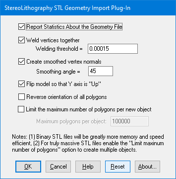
The following information explains the various options on the dialog box:
Report Statistics About the Geometry File
If this checkbox is enabled then the import converter will print out the number of objects and polygons that were parsed from the file.Weld Vertices Together, Threshold =
Polygons read in from a .stl file are, by nature, completely separate from each other and do not share vertices even if two adjacent polygons are situated side by side. This is quite inefficient and also it will not allow the .stl data to be “smoothed” out using the smoothing option described below. To overcome these problems the “Welding” option can be enabled (check-marked). Vertex welding collapses adjacent vertices which are within a distance less than or equal to the threshold value specified on the dialog box This welding operation should be performed if the “Create Smoothed Vertex Normals” option (see below) is enabled. Also, the welding operation can become quite slow for objects with large number of vertices since every vertex must be compared against every other vertex (an n-squared problem). This option is enabled by default.Threshold Value Type-In
If the distance between two vertices is less than or equal to this number, and the “Weld Vertices Together” checkbox is check-marked (enabled) then the two vertices will be collapsed (welded) into one. Since no edge in a .stl file should be shorter than 0.00015 units, the minimum value for this threshold value should be set to 0.00015 (which is the default).Create Smooth Vertex Normals
All .stl files do not contain vertex normals and thus will not look smooth when shaded. This option, when enabled, will allow smoothed vertex normals to be computed for the data based on the angle between adjacent polygons.The smoothing criterion is based on the angle between adjacent polygons; common smoothed vertex normals will be computed if the angle between their geometric surfaces normals is less than the “Smoothing Angle” type-in value described below.
If this checkbox is disabled (un-checkmarked) then no new vertex normals will be created.
NOTE: for this option to work properly the input data must have its vertices welded together so that adjacent polygons share the same vertices (the “Weld Vertices” checkbox must be enabled (check-marked)). This option is enabled by default.
Smoothing Angle Type-in This type-in value sets the cut-off smoothing angle (in degrees) used by the vertex normal computation algorithm. If the angle between two adjacent polygons is greater than this number then no smoothing will occur (a crease will be evident between the two polygons), else smoothing will occur where the polygons meet. The default angle is 45 degrees; higher values will make the surface smoother.
Flip Model so that Y Axis is 'Up'
If this checkbox is enabled then the model will be reorientated so that the “Up” axis of the model will be aligned with the positive Y axis (which is used by the converter) instead of the positive “Z” axis as used by .stl files. This option should be enabled by default.Reverse Orientation of All Polygons
If this checkbox is enabled then the orientation of each polygon will be reversed so that the polygons’ normals point in the opposite direction. By default this option is disabled.

