| You are here: Home » Import CAD Formats » AutoCAD-Revit-Navisworks (DWF-3D) |
|
This geometry import converter reads in LightWave binary object files (.lwo v2) and ASCII scene files (.lws v3). It is a very complex converter, and one of the most developed in Okino software, that will allow you to read in LightWave files and and convert or render them right away with only minor changes necessary to the imported scene.
This LightWave importer, and its corresponding exporter, have long been two of the most important converters in Okino software for many of our dedicated game development, animation and content development users. These converters, for example, allow data to be moved from LightWave, into 3ds Max, and back again with little or no degradation in scene content (including hierarchy, object and camera animation, bones + skinning, automatic bitmap conversion and so forth).
Note: if your files are written in the newer LightWave 2017+ file format then please re-export the LWO and LWS files as "LightWave 2015" format (ie. LWO v2 and LWS v3) from the current release of the Newtek LightWave software. This will rewrite the material definitions to the variations handled by Okino software.
Main Enables2 Units Animation Miscellaneous
Runtime Usage Notes
- If the import converter reports that it cannot find a particular LightWave object file (.lwo) or a bitmap texture (.iff) then add a new path to the directory where these files reside via the 'Preferences/Configure File Search Paths' menu option of the main program.
- If the import converter cannot find any of the .lwo files, when importing a .lws scene file, then you need to properly set up the 'Path to Content Directory' option. See explanation below.
- If you want to accurately import interpolated keyframe animation data from a LightWave 6 .lws scene file then enable 'Keyframe Resampling'.
Major Features of the LightWave Importer
- Reading of all LightWave supported polygon geometry,
- Reading of animation and envelope keyframe animation data. The degree of this keyframe data converted to other export file formats is dependent upon the export converter in question.
- Reading of LightWave 6 or newer bones and mesh skinning for character animation deformations. LightWave is a bit unusual in its method of defining bones, as the bones are defined as child attributes of each mesh object whereas in most other animation packages the skeleton of bones are separate from the mesh and the vertices of the mesh are "linked" remotely to each external bone.
- Reading of LightWave "Bone deformation weight maps" and/or the exact simulation of Newtek's "bone weight falloff" algorithm.
- Reading of surfaces (materials) with multiple layers of textures enabled. Okino's NuGraf and PolyTrans programs have complete support for multiple layers of texture maps per material so this capability is put to good use when importing LightWave files. All texture mapping methods are supported for multiple layers of texture maps including diffuse surface color, luminous surface color, diffuse shading coefficient, specular shading coefficient and bump mapping.
- Reading special .uv texture coordinates files created by Cinegraphics' UVIEW program or by Okino's LightWave export converter.
- Ability to break apart each LightWave object according to the materials assigned to each polygon,
- Objects which are instanced one or more times within LightWave (cloned) are likewise instanced within NuGraf (they instanced geometry will appear below a "red" folder within the Selector Window). Thus, much memory is saved since only one true copy of the raw geometry is stored in memory for each of the instances.
- The object hierarchy within the original LightWave file is recreated exactly within NuGraf & PolyTrans.
- All cameras and lights types are supported.
- Every surface (material) attribute is mapped to equivalent NuGraf surface attributes.
- All texture mapping types are supported (diffuse, specular, spherical environment mapping, etc).
- All of the LightWave texture projection methods are supported, including planar, spherical, cylindrical and cubical. These projection methods are converted directly to equivalent NuGraf projection methods. The conversion is exact, so the textures should appear faithfully when rendered within NuGraf or when the data is exported to another file format (such as 3D Studio, VRML or Wavefront).
- An IFF image format reader has been added to the NuGraf & PolyTrans software so that it can directly read in the LightWave IFF-formatted texture maps.
- Automatic scene, geometry and bones scaling so that the measurements units of the source LightWave file match the measurements units of the destination program (in particular, 3ds Max, Maya, CINEMA 4D, COLLADA, FBX, glTF, U3D, DirectX, etc).
- Application of automatic or forced subdivision surfaces to imported meshes, using all major subdivision surface techniques.
- Reads in vertex normals stored in the Newtek LightWave 9.6+ and Luxology MODO VMAP/MVAD chunks (type = "NORM", name = "vert_normals").
Additional Features for LightWave 6-or-newer File Format
With the release of the updated LightWave file format, this converter can also:
- Import uv texture mapping coordinates which did not exist in the older 5.6 file format. This is one of the more demanding aspects of this current LightWave importer. Both the VMAP chunk of LightWave 6+ (per-vertex uv mapping) and the newer VMAD chunk of LightWave 6.5+ (per-vertex-per-polygon uv mapping) are handled properly.
- Import RGB per-vertex color values. Again, this is one of the more demanding aspects of this LightWave importer. Both the VMAP chunk of LightWave 6.0+ (per-vertex RGB color mapping) and the newer VMAD chunk of LightWave 6.5+ (per-vertex-per-polygon RGB color mapping) are handled properly.
- Import objects with no restriction on size. There is no longer the 65536 limit on the number of vertices or polygons per .lwo file that was an inherent problem with LightWave 5.6 or older files.
- Provide complete LightWave layer support, including the segmentation of polygons by their assigned layer name, creating object hierarchies based on the assigned layers, assigning animation data on a per-layer basis and importing specific layers from a .lwo file (by providing a layer number reference in the LoadObjectLayer command of the .lws file).
- Parse the new segmented animation and envelope syntax of the .lws scene file. In v5.6 or older, all scale, rotate and translate animation values were specified at the same time for each keyframe. With LightWave 6+ the scale, rotate and translate animation channels are specified in 9 successive sections while provides cleaner support for animation in LightWave.
- The new layered texture channel BLOK system is parsed, manipulated and recreated within the import process. This importer will handle unlimited layers of diffuse, specular, opacity, bump and other texture modulation channels; however, not all 3D rendering and animation packages can handle unlimited layers of texture.
Notes about the Import of LightWave Bones
Okino's LightWave importer supports the most complete possible range of LightWave skinning options. It supports explicit vertex weights assigned from weight maps, implicit vertex weights calculated from both limited-range and unlimited-range bones, and overlay/blending between explicit + implicit vertex weights. It also supports all bone strength and falloff parameters, including limited-range calculations and "Faster Bones" optimizations. Bone pivots are also completely supported.
The only exceptions are the "Joint Compensation" and "Muscle Flex" parameters, which are proprietary LightWave algorithms and as such cannot be replicated in other skinning systems. These are not handled during import.
Bones can be imported with skinning data disabled, but skinning data requires a set of bones in order to be meaningful/possible.
The implicit vertex weight calculations are convoluted, but we have based our solution directly on code provided by Newtek. The blending/normalizing of weights is non-standard and non-trivial. Since LightWave calculates delta-deformations, the Okino LightWave importer may need to add a dummy bone representing the non-deformed mesh.
The bone weight falloff algorithm that has been implemented in the Okino LightWave importer follows the LightWave algorithm to the letter. Generally speaking, the strength of a bone degrades based on the distance between the bone and the vertex. However, effects are normalized, so a vertex influenced 1e-5 by only 2 bones may as well be influenced 50%-50% between those bones. Applying "limited range" to the bones alters the falloff profile in a somewhat non-intuitive way. Part of the issue is that certain weights can still be counted for the purposes of normalization, even when they are not ultimately used for deformation.
The Okino LightWave importer converts any implicit vertex weights into purely explicit vertex weights as part of the import process, since this is the format readily accepted by other 3D packages.
Description of the .lws and .lwo File Standards
LightWave uses two primary files, a .lws scene file and multiple .lwo object files:
- The raw geometry for each object is stored In a separate file called a LightWave Object File. Normally it has a file extension of .lw, .lwb, .lwobj or sometimes no extension at all. These files are binary and cannot be read directly.
- The scene setup description file is stored in a single file called a LightWave Scene File. Normally it has a file extension of .scene, .scn or it must use a descriptive filename such as "Load Up The Entire Scene". This file is human readable and can be edited with a normal text editor.
Limitations of the LightWave Import Converter
- LightWave allows a different texture projection type to be assigned to each texture layer applied to a surface (ie: spherical for the color texture, cylindrical for the bump texture). NuGraf and PolyTrans only allow one, so it chooses the first texture projection type assigned to the surface.
- "Detail" polygons are created as separate polygons. This might cause problems when rendered in the destination program.
- UVIEW files are only supported for the older LightWave 5.6 files. For LightWave 6.0 or newer, the UVIEW program itself will output LightWave 6+ compatible uv coordinates and no longer has to use the .uv external files.
- The "front" texture projection method is not supported. The planar, cylindrical, spherical and box projection modes are fully supported.
"Main Options" Dialog Box Options:
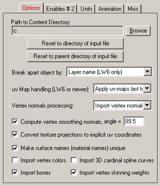
The following information explains the various options on the dialog box:
Path to Content Directory
Most often, LightWave scene, object and image files are stored in a hierarchical directory structure in which all the scene files (.scn files) are located in a 'scenes' directory, the objects (.lwo files) are stored in a 'objects' directory and the images (.iff) are stored in a 'images' directory. For example, the scene files on the LightWave distribution CDROM are stored in this manner. In order for this import converter to locate the files, the 'Path to Content Directory' option must be set so that it points to the single directory which holds the 'scenes', 'objects' and 'images' directory. To read in the LightWave scene files from the LightWave distribution CDROM, for example, set this directory path to point to 'c:\newtek' (if indeed you installed LightWave in 'c:\newtek'). To change the directory path press the 'Browse' button and choose the new root content directory.The two buttons located below this type-in box provide a fast way to set the Content Directory path. If you know that the path to the Content directory is the same as the path selected for the .lws or .lwo file, then press the "Reset to Directory of Input File". Else, if you know that the path to the Content directory is the parent of the path selected for the .lws or .lwo file, then press the "Reset to Parent Directory of Input File". For example, if you selected the LightWave scene file "c:\test\scenes\test.lws" and the content directory (which contains the images, objects and scenes sub-directories) is the "c:\test" directory, then press the "Reset to Parent Directory of Input File" button.
Break Apart Object By... (Combo Box)
One of the advanced internal features of this LightWave importer is its ability to break apart (explode) a LightWave .lwo file by assigned surface (material) name, layer name (LightWave 6.0 or newer) or a combination of these two methods.Disabled. Don't break apart object.
If this checkbox is enabled (check-marked) then the .lwo object file is imported as-is without any change.Surface (Material) Name
If this checkbox is enabled (check-marked) then each imported LightWave object will be exploded into separate sub-objects based on the surface (material) names assigned to the polygons in the objects. This is a useful option because it will allow you to modify the various sub-pieces of each object much easier than if you do not explode the object.Take for example an object which is a human head. All of the polygons are stored in a single LightWave object. The head has multiple surfaces assigned to it, including a surface for the mouth, eyes, hair, face and eye brows. By enabling this option the human head will be exploded into separate sub-objects.
Layer Name (LW6 or newer only)
If this checkbox is enabled (check-marked) then the imported .lwo file will be exploded into sub-objects based on the layer name to which they have been assigned. With LightWave 6+, a single .lwo file can contain a single object with multiple object layers defined, and the polygons of the .lwo file can be segmented by assigning them to the different layers. If there are 2 or more layers in the final exploded object then they will be grouped together under a new empty-instance folder.If you import the .lwo file via the 'LoadObjectLayer' command in a .lws scene file, and the layer number provided with this command is greater than 0 (0 means to load in all layers), then only a single layer is imported from the .lwo file.
Surface and Layer Name (LW6 or newer only)
If this checkbox is enabled (check-marked) then the imported .lwo file will be exploded first by its assigned layer names and then by the assignment of surface (material) names for each polygon.uv Map Handling (LightWave 6 or newer)
LightWave 6+ finally introduced the all-important concept of uv texture mapping to its new file format. Prior to version 6 these uv coordinates could not be transferred from other 3D programs into LightWave since LightWave 5.6 did not handle these uv values. uv coordinates describe how a flat 2d texture map is to be mapped to an arbitrary location on a 3D object.
However, the new uv texture mapping system of LightWave provides just a bit too much generality to allow every possible variation of uv mapping to be converted to other 3D programs. In LightWave 6 each and every texture map can have its own set of uv texture coordinates (called a 'uv map'). This provides great generality since a single mesh object could potentially have one or more surfaces assigned to it (materials), and each material could have an unlimited number of texture maps (texture decals) each of which uses its own set of uv texture coordinates or its own uv texture projection icon.
Unfortunately, many 3d file formats only allow one set of uv texture coordinates to be associated with the raw mesh itself, and not an unlimited number to be associated with each texture layer. This importer must convert from the uv-map-per-texture method to the uv-map per mesh method.
The importer uses an intelligent algorithm to create a single uv-map for the entire mesh. It basically applies the LightWave 6 uv maps to the mesh object, texture layer by texture layer until all layers of all materials have been considered for the mesh.
The options of this drop-down box determine in which order the uv-maps are applied to the mesh object:
Apply uv maps last to first
The uv-maps are applied from last to first. For example, if a surface (material) has 4 texture layers assigned to it, and each layer has a different set of uv coordinates or texture projection methods, then the uv coordinates will be applied to the method starting from the last texture layer and proceeding to the first texture layer. This ensures that at least the first texture layer will get rendered properly in the destination package.Apply first uv map only
Only the uv coordinates from the first texture layer are used to create the uv coordinates for the imported mesh.Apply last uv map only
Only the uv coordinates from the last texture layer are used to create the uv coordinates for the imported mesh.Vertex Normals Processing
This combo box determines if the vertex normals from the .lwo file should be imported or ignored. In general, use the default value. If you are importing from older Modo files, and find that the vertex normals look wrong or an inverted, then choose the third combo box option.History and background:
Prior to 2007 the LightWave .lwo file format never supported "vertex normals". This mesh attribute is quite important, as it defines the overall smoothness of mesh models and is most critical to the import of CAD models via the .lwo flile format (such as those exported by Okino software). In 2007, Luxology (the developers of the Modo CAD program, and the original LightWave software developers) devised a new chunk called "vert_normals" that allowed such vertex normals to be stored within the .lwo file. A few years later Newtek released LightWave v9.6 which also supported this new explicit "vert_normals" chunk. Unfortunately, older/original versions of Modo did not negate the "Z" component of the vertex normals as is required by the LightWave v9.6 file format standard and hence you'll need to choose the third combo box option for those older files.No not import explicit vertex normals
If this combo box option is chosen then the explicit vertex normals found within the .lwo files will be ignored and not imported. Then, if the Compute vertex smoothing normals checkbox is enabled, new normals will automatically be computed for each mesh based on vertex connectivity (which is only approximate).Import vertex normals (LW 9.6+ and newer Modo files, flip 'z')
If this combo box option is chosen then the vertex normals for each mesh object will be taken from the "vert_normals" chunk within each .lwo file, if it exists. This only exists for files written by (1) LightWave 9.6 or newer, (2) newer versions of Luxology's Modo program, (3) Okino software after May 2007. This is the default value.Import vertex normals (Older/original Modo files, no 'z' flip)
This is the same as above, but the "Z" component of the vertex normals will not be negated. This should be chosen when .lwo files are being imported from older/original versions of Modo whereby the vertex normals were written in "Right handed coordinates" instead of the proper "Left handed coordinates" as is used by the Newtek LightWave software. Basically, you should choose this option if you feel that the imported vertex normals look incorrect (they are inverted).Compute vertex smoothing normals
If this checkbox is enabled then new vertex normals will be computed for the raw imported geometry. These vertex normals are required if the geometry is to appear smooth when rendered.The smoothing criterion is based on the angle between abutting polygons; common smoothed vertex normals will be computed if the angle between their geometric surfaces normals is less than the angle specified on the dialog box (which defaults to 89 degrees). This value will be overridden if a LightWave surface definition has a smoothing angle specified for it.
Convert Texture Projections To Explicit uv Coordinates
LightWave has two primary methods to specify how texture maps are to be aligned to polygons of an object: texture projections (such as planar, cylindrical, spherical and box), or via explicit uv texture coordinates (the latter only for LightWave 6.0 or newer).If this option is enabled then the texture projections which are associated with a LightWave surface definition will be converted to explicit uv texture coordinates during the import phase. In general you will want to keep this option enabled for the most accurate texture mapping.
If this option is disabled then the LightWave texture projections will be turned into equivalent internal Okino texture projections; the Okino texture projections will only be converted to explicit uv texture coordinates during a rendering process or when the mesh is re-exported. The correspondence between the LightWave and Okino texture projections are 1-to-1 (identical). However, LightWave assigns texture projections to each texture layer of a material while Okino software assigns texture projections on a per-object basis. Thus, if a LightWave object has 2 or more different texture projections assigned to it then you will have to change the "Break Object Apart By..." combo box option to include the "By Surface Name" option. This is necessary to that the mesh gets exploded by surface (material) name and thus Okino software can apply its texture projection icon to each new object properly.
Make Surface Names (Material Names) Unique
If this checkbox is enabled (check-marked) then the import converter will append each imported surface name (material name) with a number to make it unique should it find that the name is already defined in the internal 3d scene database. For example, if the same LightWave object file is imported twice in succession (which includes a surface called 'car_red') then the import converter will rename the second surface to 'car_red # 2' so that it will not conflict with the first imported surface called 'car_red' (even though they are identical surface definitions). The checkbox is enabled by default.If the checkbox is disabled (un-checkmarked) then the import converter will not make the surface names unique even if an identical surface name exists within the 3d scene database. You may want to disable this option so that multiple geometry meshes share the same surface definition.
Import Vertex Colors
If this checkbox is enabled (check-marked) then vertex colors will be imported and assigned to the mesh polygons.Import 3D Cardinal Spline Curves
If this checkbox is enabled (check-marked) then 3D cardinal spline curves will be imported into PolyTrans/NuGraf as equivalent cardinal splines. If these curves have to be imported intoa NURBS-based modeler (like Maya) then PolyTrans will automatically resample the Cardinal spline into a NURBS curve.Import Bones
If this checkbox is enabled (check-marked) then the skeleton of bones which are assigned to a mesh object will be imported. LightWave is a bit unusual in its method of defining bones, as the bones are defined as child attributes of each mesh object whereas in most other animation packages the skeleton of bones are separate from the mesh and instead the vertices of the mesh are "linked" remotely to each external bone. See also the Notes about the Import of LightWave Bones section above.Import Vertex Skinning Weights
If this checkbox is enabled (check-marked) then the Bone deformation weight map will be imported along with each mesh object. These weight maps are used during real time mesh deformation using bones, as the weights define how much each vertex is to move relative to the movement of its associated and assigned bone.Also, this importer has an exact simulation of Newtek's "bone weight falloff" algorithm and thus turns the fall-off weight values from the source files into explicit bone weights during the import process. See also the Notes about the Import of LightWave Bones section above.
"Enables Panel # 2" Dialog Box Options:
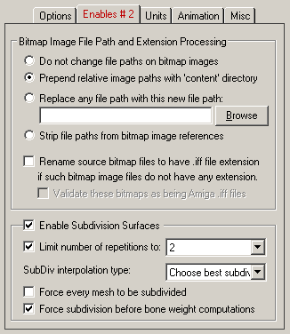
Bitmap Image File Path Processing
These radio buttons determine what type of processing will be done on any bitmap image filenames and filepaths imported from the .lwo files.Do change change file paths on bitmap images
If this radio button is selected then the bitmap filepath and filename will remain unchanged.Prepend relative image paths with 'content' directory
If this radio button is selected and the filepath imported from the .lwo file is itself relative (not absolute, such as c:\Newtek\images\file.iif"), then the value of the "Content Directory" will be pre-pended to the imported image filename. For example, if the original imported filename is "images\test.iff" and the Content Directory is "c:\Newtek" then the final bitmap filepath will be "c:\Newtek\images\test.iff".Replace any file path with this new file path:
If this radio button is selected then the filepath of the imported image filename will be stripped off and replaced with the filepath shown in the type-in line. Press the Browse button if you wish to select a new filepath.Strip file paths from bitmap image references
If this radio button is selected then the filepath will be removed completely from the bitmap image filename imported from the .lwo file.Bitmap File Extension Processing
These two checkboxes define options which come in very handy, but in rare cases. There are cases where bitmap images have no file extensions; this was often the case for IFF bitmap images used with the Amiga version of LightWave. However, this import converter needs to always have a valid file extension, IFF in this case. Thus, these two options allow proper file extensions to be added.Rename source bitmap files to have .iff file extension if such bitmap image files do not have any extension.
If this checkbox is enabled (check-marked) then any bitmap image filename which does not have any extension on it will be appended with the .iff extension (Amiga IFF file format).Validate these bitmaps as being Amiga .iff files
If this checkbox is enabled (check-marked) then the import converter will only append the .iff file extension if it can verify that the bitmap image is indeed in the Amiga IFF file format.Subdivision Surfaces
These options control automatic subdivision of imported mesh objects. "Subdivision" adds more polygons to an otherwise low quality mesh. LightWave objects are often created using "Subdivision surface modeling", for which the base mesh (non-subdivided mesh) is stored in the .lwo file.
Subdivision is a way to smooth out the surface details of a geometric mesh. The polygons on the original mesh are split according to a set of subdivision rules, and in some cases the vertices on the original mesh are moved to smooth out corners.
The quality of the final subdivided mesh is affected by two factors: the number of subdivision levels used and the topology of the original mesh. If a model was not made with subdivision in mind, problems can occur. However, if a mesh was made specifically for one type of subdivision, the model will only look good when subdivided.
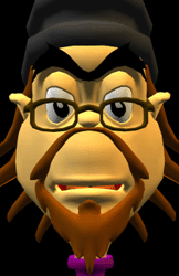
("William", from the Newtek LightWave contents CD)
The "William" model was made in the LightWave subdivision modeler.The image on the left is the original mesh, and the following three images are the Catmull-Clark routine applied one, two and three times. As you can see, the model looks very poor in its original state, but even after one level of Carmull-Clark subdivision it looks very close to what the artist who created it would have seen. Increasing the levels of subdivision to 2 yields better looking results. The third subdivision level looks only slightly better than the second subdivision level. From this one can see that higher levels of subdivision give diminishing returns. This is good to keep in mind since memory requirements go up dramatically for each level of subdivision applied.
Enable Subdivision Surfaces
This checkbox controls whether the subdivision algorithm will be allowed to execute. It is enabled by default.
Note: if a mesh object is tagged as a "patch" inside the .lwo file, then the subdivision algorithm will be invoked to subdivide that single mesh further. Otherwise, all other "normal" meshes will not be subdivided unless the "Force Every Mesh To be Subdivided" option is enabled.
Limit Number of Subdivisions to #
This combo box allows you to limit the number of subdivision iterations made. Each iteration will significantly increase the number of polygons. Usually you will want to choose 1 or 2. 2 is the default.
The number of subdivision iterations will be taken from the .lwo file for meshes tagged as "patches". This number is often too high (such as 3 or 4), and thus this combo box can be used to limit the maximum number of iterations actually used.
Subdivision Interpolation Type:
This combo box determines which of the 4 main subdivision techniques will be used on each mesh.Catmull-Clark (non-interpolating, quads or triangles)
This subdivision technique is best used on quads only.Loop (non-interpolating, triangle input only)
This subdivision technique is best used on triangles only.Butterfly (intepolating, triangle input only)
This subdivision technique is best used on quads only, and when the source mesh is of very low detail and quality, and has no relatively complicated sectionsKobbelt (interpolating, quad input only)
This subdivision technique is best used on triangles only, and when the source mesh is of very low detail and quality, and has no relatively complicated sections.Choose best subdivision algorithm automatically
This combo box selection will automatically choose the best subdivision technique based on each mesh presented to it.Force Every Mesh To be Subdivided
By default only LightWave .lwo meshes which are tagged as "patches" (SubDiv meshes) will be automatically subdivided during import.If this checkbox is enabled then every single mesh in each .lwo file will have subdivision applied to them. The number of iterations will be set via the "Limit Number of Subdivisions" combo box.
Force Subdivision Before Bone Weight Computations
In order to allow implicit skinning weights to survive the subdivision process, the subdivision process must be invoked before the fall-off algorithm is used to explicitly calculate the skinning weights. Enabling this checkbox will force the subdivision operation to come before the skinning weight calculations. Disabling this option will cause the order of skinning/subdivision to be determined from the data contained inside the .lwo file. NOTE: at present we do not support the case of subdividing the mesh after the skin weights are computed inside the LightWave importer. If this order of operations is used then no skinning weights will be available on the final imported mesh.
"Units" Dialog Box Options:
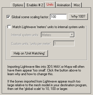
Global Scene Scale Factor (= 100 by default)
This type-in edit box allows the entire imported LightWave scene to be scaled larger or smaller. Values greater than 1.0 scale the scene larger whereas values less than 1.0 (and larger than 0.0) scale the scene smaller.This option was added for pure perceptual reasons. If you import a LightWave file into 3DS MAX or Maya, for example, you will find that a model appears to be much smaller than you would normally expect. This has more to do with how each of these animation programs set up their default cameras. From our obervations LightWave users tend to create small models, those that falls within one or a few grid lines inside LightWave, whereas in 3DS MAX the camera is much further away from the default grid and thus objects tend to be 10 to 100 units wide by the very nature of the camera's default location. Thus, the default scale factor has been set to 100 so that the imported Lighwave scene covers more of the default grid area inside 3DS MAX or Maya.
Match LightWave 'meters' Units To Internal System Units
This import panel determines what will be done when the units defined in the LightWave file do not match the current internal system units. If the units do not match, the importer will rescale the imported LightWave geometry based on the ratio between LightWave's meter units and the internal system units.LightWave explicitly uses "meters" for its unit of measurement. This means that a cube "1 unit wide" can be considered "1 meter wide" within the LightWave software. However, when that same "1 meter wide" cube is moved to Autodesk Maya (for example) it now appears as "1cm wide" because Maya associates "1 raw unit" to "1 centimeter" as its basic unit of measurement. PolyTrans itself flows polygon data from one program to another as unitless, "raw" data and it is up to the destination program to decide how to interpret the unitless data as some specific "size". The options on this panel help alleviate the differences in the 'units of measurement' from one 3D program to another.
The options on this panel allow the scene to be automatically scaled larger or smaller to match a "desired" units of measurement compared to that which is specified in the LightWave file. For example, if you are importing into Maya via the native PolyTrans-for-Maya plug-in system then the drop-down combo box will automatically be set to "Centimeters" by the plug-in system; this will cause a "1 meter wide" box from LightWave to be scaled up 1000 times before being imported into Maya.
"Animation" Dialog Box Options:
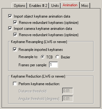
One of the advanced features of the PolyTrans software is its ability to clone the object and camera keyframe animation capabilities of the major 3D animation packages such as LightWave, 3ds Max, Cinema-4D and Maya. The following options control how object and camera animation data is handled during the import process.
Import object keyframe animation data
If this checkbox is enabled then animation data assigned to mesh and null objects will be imported as scale, Euler rotation and translation keyframe lists. If animation data is assigned to specific layers inside a .lwo file then only those layers will be imported and animated (this is how LightWave works).Import camera keyframe animation data
If this checkbox is enabled then animation data assigned to cameras will be imported. Location, orientation and zoom (field of view) animation channels will be handled.Keyframe Resampling (LightWave 6 or newer)
If you want accurately interpolated keyframe animation data to be imported from the LightWave .lws scene file, then enable this option.
Enabling this option will cause the importer to create a new keyframe at every frame of an imported animation curve. With the development of this new LightWave 6 importer, the actual animation curve interpolation algorithm from the LightWave 6 program itself was incorporated into this importer. Thus, the newly resampled keyframe values should be identical to the values as seen inside LightWave 6 itself.
In addition, this importer will automatically enable keyframe resampling if it detects that an animation curve uses a mixture of different interpolation methods. LightWave 6 is unusual in its ability to mix interpolation methods in a single curve, such as constant, TCB, Bezier and linear. To import such as curve to other animation packages the curve will have to be resampled to some common standard, either a TCB curve or a Bezier curve.
Resample to: TCB or Bezier
This radio button determines if the new resampling curve should be considered a TCB or Bezier curve. You should ideally select the mode based on what curve type is used in the destination animation program. For example, Maya is Bezier based, 3ds Max is TCB or Bezier and .3ds file format is TCB.Frames Per Sample
This determines the spacing between new keys created. If the value is set to 1 then a new keyframe is created at every frame. If set to 2 then a new key is created every other frame. etc.Keyframe Reduction (LightWave 6 or newer)
The above resampling process creates one new keyframe for each frame in the current animation, hence there can be an overabundance of new keyframes in the imported animation. To alleviate this problem a robust 'keyframe reduction' algorithm was added to the new LightWave 6 importer which intelligently removes some or most of the re-sampled keyframes. The resulting imported animation will exhibit the same or similar behavior, but with much fewer keyframes. If this checkbox is not enabled (not check-marked) then no keyframe reduction will be performed.'Distance' Difference Threshold
This numeric value indirectly controls how many redundant keyframes are to be removed from the re-sampled keyframe list. It is applicable to the following types of keyframe lists: translation, scaling and path translation. Higher values will cause more keyframes to be removed. This value is the maximum 'distance' the new keyframe list is allowed to deviate from the original re-sampled keyframe list. Take for example a sphere that is animated along a path; if this threshold value is set to 0.5 distance units (which is the default) then redundant keyframes of the animated path will be removed until such point that the sphere begins to deviate by more than 0.5 units from its 'ideal' location. In other words, if the value is set to 0.5 then you are guaranteed that the new reduced keyframe list will move the sphere along the same path in space, except that the sphere is allowed to deviate by 0.5 units from its original path. Smaller numbers will make the sphere adhere closer to its original path, but at the expense of retaining more keyframes.Angular Distance Threshold (Degrees)
This is the same as the previous numeric value except that it applies to reduction of Euler rotation keyframe lists. The value is measured in degrees. For example, if set to 5.0 (the default) then redundant keyframes will be removed from a keyframe list until such point that a rotation angle begins to deviate from its ideal angle by more than 5 degrees. Small numbers (such as 1.0 and 0.5) will cause less deviation and more precise rotation conversions, but at the added expense of retaining more keyframes.
"Miscellaneous" Dialog Box Options:
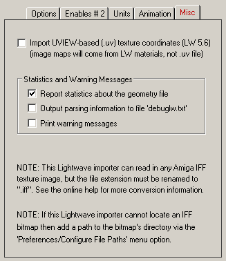
Import UVIEW-Based (.uv) Texture Coordinates (LightWave 5.6 only)
This is a handy and useful feature that allows uv texture coordinates to be input for an object from a UVIEW ".uv" ASCII file (and not from the embedded UVIEW binary information). These files are output from the UVIEW program created by "Cinegraphics" (at www.cinegraphics.net, 619-677-3908, info@cinegraphics.net) and by Okino's LightWave export converter. Please note that the coordinates must be output as a .uv ASCII file and not as embedded binary uv coordinates within the LightWave .lwo files. Also, this UVIEW import process will only work for older lightwave 5.6 files. For LightWave 6 or newer, the UVIEW program itself will output embedded uv texture coordinates within each .lwo file, so there is no longer a need for the external .uv files.If this option is disabled then the texture coordinates from each object will be created on-the-fly from the texture projections currently assigned to the materials which themselves are assigned to the various polygons of each object. If this option is enabled then uv coordinates from the .uv file will override any internally created uv texture coordinates. The .uv file must have the same base filename as the .lwo object file for which the uv texture coordinates are to be applied.
Report statistics about the geometry file
If this checkbox is enabled then the LightWave geometry import filter will report the number of polygons and vertices read from the file.Output parsing information to file "debuglw.txt"
If this checkbox is enabled (check-marked) then verbose information about each LightWave object and scene file parsed will be output to the text file "debuglw.txt" in the current working directory. This file will describe each file's contents in detail (polygon counts, material names and detailed material descriptions).Print warning messages
If this checkbox is enabled then any warnings reported by the LightWave geometry import filter will be printed to the messages window.Note # 1 describes that this importer and the PolyTrans software can read Amiga IFF files which is the standard file format used by LightWave. However, each file must have the .iff file extension added to it. Also, be forewarned that Maya also uses the .iff designation for their IFF based bitmap images as well. This converter has an internal mechanism to determine if the file format is in the Amiga or Maya (Alias) IFF file format.
Note # 2 describes that the PolyTrans stand-along software, PolyTrans-for-Maya and PolyTrans-for-MAX can search for a bitmap by having a texture search path added to the 'Configure File Search Paths' dialog box.


