

| You are here: Home » Import CAD Formats » NGRAIN's 3KO Solutions |
Support: 905-672-9328 Copyright © 2026 Okino Toronto, Ontario, Canada. |
|
Okino's Free XAML Viewer
Overview
Online Scene Demos (XAML Files Exported by PolyTrans)
What is XAML?
Dialog Box Option Panels
Example XAML 3D File
Features of the XAML Export Converter
Current XAML Export Converter Limitations
How to Load XAML Files into MS Expression Blend
Creating & Using Control Template Files
This page describes the intelligent and well implemented Okino XAML file converter module which allows all varieties of 3D geometry, hierarchy, materials, textures and animation to be exported to native Microsoft .xaml files.
The Okino XAML exporter acts as a middleware tool. It imports from almost every major 3D CAD, DCC and VisSim file format, then optimizes/reduces/composes the scene data, after which the scene data is exported cleanly out to an ASCII .xaml file. Downstream UX authoring programs then import the 3D XAML files to compose a .NET user interface.
For example, this exporter can take complex 3D scenes from Maya, 3ds Max, CINEMA 4D, Maya, LightWave, all major CAD assembly formats, (and many other 3D programs), turn them into compliant XAML files, then use them for Microsoft Windows button creation, hit targets, form controls, and much more in a downstream UX design program.
The next generation of Microsoft Windows user interface keeps UI content in a pure vector format, so the user interface can scale without losing quality (including the embedded 3D XAML data).
NOTE: This exporter does not require that the Microsoft .NET v3 (or newer) runtime environment be installed on your computer. The export to XAML is done independently of .NET v3. Only the Okino free XAML viewer requires .NET v3.
Click on any image below to jump to the scene demos WEB page:


As quoted from Wikipedia:
"XAML (short for Extensible Application Markup Language, and pronounced "Zammel") is the user interface markup language for the Windows Presentation Foundation, which is one of the "pillars" of the .NET Framework 3.0 API.
XAML is a declarative XML-based language optimized for describing graphically rich visual user interfaces, such as those created by Macromedia Flash. XUL and UIML are other examples of XML-based user interface languages. Okino's XAML exporter creates 3D objects for use by down-stream XAML authoring programs.
XAML was designed to support the classes and methods in the .NET Framework that deal with user interaction, especially screen displays."
Main Enables
Mesh Materials
File Paths Animation
![[2]](exp_xamlsml2.gif)
![[5]](exp_xamlsml4.gif)
![[1]](exp_xamlsml1.gif)
![[3]](exp_xamlsml3.gif)
![[7]](exp_xamlsml5.gif)
![[4]](exp_xamlsml6.gif)
The following is a (simplified) example of a XAML file containing one 3D polygon, two directional lights and one assigned material.
<Viewport3D x:Name="OkinoViewport3D" ClipToBounds="true" Width="400" Height="300"> <Viewport3D.Resources> <ResourceDictionary> <MaterialGroup x:Key="default"> <DiffuseMaterial> <DiffuseMaterial.Brush> <SolidColorBrush Opacity="1" Color="#EECCDD"/> </DiffuseMaterial.Brush> </DiffuseMaterial> </MaterialGroup> </ResourceDictionary> </Viewport3D.Resources> <Viewport3D.Camera> <PerspectiveCamera x:Name="default" Position="20,15,20" UpDirection="0,1,0" LookDirection="-0.624695,-0.468521,-0.624695" FieldOfView="28.0725" /> </Viewport3D.Camera> <ModelVisual3D> <ModelVisual3D.Content> <Model3DGroup> <DirectionalLight Direction="-1,1,1" Color="#FFFFFF"/> <DirectionalLight Direction="1,1,1" Color="#FFFFFF"/> <Model3DGroup x:Name="rectangle"> <GeometryModel3D Material="default"> <MeshGeometry3D TriangleIndices="0 2 3 0 3 1" Positions="-2,-2,0 -2,2,0 2,-2,0 2,2,0" Normals="0,0,1 0,0,1 0,0,1 0,0,1" TextureCoordinates="0,0 0,1 1,0 1,1" /> </GeometryModel3D> </Model3DGroup> </ModelVisual3D> </ModelVisual3D.Content> </Model3DGroup> </Viewport3D>
- An "intelligent" 3D exporter that can reconfigure its XAML output structure in a variety of ways to provide for great flexibility in repurposing any 3D scene into a properly formatted XAML 3D document.
- A plethora of options across 6 panels to provide you with great control over the XAML scene export process. Many options have also been added during the development process of this exporter which help smooth quirks associated with 3D XAML files, or which help create a "nice looking 3D model" in downstream XAML viewers without having to tweak the source scene by hand.
- All main Okino 3D primitives will be converted and output as XAML triangular meshes with vertex normals and (u,v) texture coordinates.
- Output of the geometry hierarchy using the XAML
tag.
- Exports point, spot and directional light sources and their related parameters. 18 predefined light configurations are made available, which allows lights to be automatically added to the exported XAML scene if none are available in the source scene.
- Perspective or orthographic cameras.
- Material export including ambient/diffuse/specular/luminous colors, shading coefficients, associated texture maps, opacity, Phong shininess and UI options to override or tweak any of these parameters prior to exporting.
- Mesh geometry tweaking, modification and transformations via automated operations made available by Okino's suite of polygon reduction and transformation routines. Ideal as a means to "clean up" the source meshes and apply 80-95% pre-polygon reduction to the models prior to export to XAML.
- Animation, of varying levels of implementation.
- Multiple methods to output the XAML file with a different structure, some utilizing the "resource" capability of the XAML file format, and another allowing control templates to be defined.
- Exports point, spot and directional light sources and their related parameters. 18 predefined light configurations are made available, which allows lights to be automatically added to the exported XAML scene if none are available in the source scene.
Relatively speaking, compared to most other file formats, XAML is a very simple file format for 3D data. However, when combined with other XAML content and tagged with animation/behaviors in a XAML authoring program, the resulting interactive and scalable user interface is very powerful and compelling.
The following are the most important limitations that should be described:
- All meshes will be triangulated.
- No vertex colors are accommodated on meshes.
- The vertices, normals and uv texture coordinates for a mesh must share the same "index array". This can result in larger file sizes due to duplicated vertices, normals and uv texture coordinates.
- XAML only has a 3D triangle primitive. No 3D points, polylines, spline shapes or NURBS surfaces will be output. Spline shapes and NURBS surfaces will be converted and output as triangle meshes.
- XAML material definitions are rather simple. Either a uniform color (solid brush) or texture map (image brush) will be output for diffuse, specular and luminous shader channels, but not both.
- There is no way to enable or disable texture wrap-around flags for both the U and V directions. Either wrap-around (tiling) is enabled, or it is disabled for both the U and V directions.
- There is no way to specify the scale and offset of each individual texture map.
- Skinned meshes with skeletons are not supported by XAML.
To create XAML files and load them into Microsoft's "Expression Blend" for viewing, follow this procedure:
- Export the 3D XAML file using the Okino XAML exporter. Set the "XAML File Structure" combo box to "Output only multiply-refereced elements as 'Resources'". Set the "XAML Control Type" combo box to "Viewbox" for simplicity and generality.
- Start up Microsoft's Expression Blend. Open an existing project or create a new project. Select a scene, or define a new scene.
- Choose "Project / Add Existing Item" from the main menu. Select the XAML file you just exported as well as all texture image maps which are referenced by that file. Press Ok on the file selector.
- The name of the XAML file you just loaded will appear in the "Projects" window of Expression Blend. Double click on that name in the Projects window. The XAML file will open for 3D interactive viewing.
Microsoft's "Expression Blend" allows XAML files to be loaded as external dictionary resources and then the 3D assets defined in the XAML file to be used as "Control Templates".
- Export the 3D XAML file using the Okino XAML exporter and set the "XAML File Structure" combo box to "Output as 'Control Template' for XAML authoring tools".
- Start up Microsoft's Expression Blend. Open an existing project or create a new project. Select a scene, or define a new scene.
- Choose "Project / Add Existing Item" from the main menu. Select the XAML file you just exported. Press Ok on the file selector.
- The name of the XAML file you just loaded will appear in the "Projects" window of Expression Blend.
- From the "Window" menu of Expression Blend make sure "Resources" is enabled.
- 6. In the "Resources" panel on the right side of Expression Blend you should see the same name as you had just loaded. If the file name does not appear then you did not create the XAML file using the "Output as 'Control Template' for XAML authoring tools" export option.
- Now we will create an instance of our new 3D resource asset and link it to a XAML UI control. As an example of how to do this, from the "Asset Library" button on the Expression Blend's vertical toolbar, drag & drop a button control to the current project. Make sure the button control is selected. From the "Resource" panel, open up the tree view entry for our imported .xaml file so that you can see the child "OkinoControlTemplate" entry. Click on the "OkinoControlTemplate" entry and drag&drop it over top of the button in the user interface. When the popup menu appears choose "Create control of type: control". The 3D model from the XAML control template file will now be assigned to the button control as an instance. You can repeat this process of applying the 3D resource to new UI controls.
- If the original 3D XAML file content is ever changed then all instances which reference it will automatically be updated inside Expression Blend.
This panel contains the XAML export options which are used most often.
XAML Control Type
XAML files consist of one or more "elements" which overall define a user interface layout. Common control elements used to "layout" (position) other sub-elements are Canvas, Dock, Grid, Stack and Wrap.
All 3D data is contained in the "Viewport3D" element type. The "Viewport3D" element is then positioned on a page/window using such common layering elements as the Canvas, Dock, Grid, Stack or Wrap.
This combo box determines which main layout control will be wrapped around the "Viewport3D" element.
Viewport3D
No layout element control will be wrapped around the "Viewport3D" element control. This option will create the most basic XAML file. If the layout is interactively scaled then the 3D data within the "Viewport3D" element will not be scaled.See the Example XAML 3D File section for a bare-bones XAML file which just uses one "Viewport3D" element control.
Viewbox
This will place the "Viewport3D" element within a "Viewbox" control. The Viewbox control is scalable, and hence the 3D data within the "Viewport3D" element will scale as the layout is interactively scaled. Only one child is allowed inside the Viewbox control so normally the Viewbox control is placed within a Canvas or Grid control.Canvas
This will place the "Viewport3D" element within a non-scaling "Canvas" control. Multiple children are allowed inside the Canvas control, with no constraints on layout design.Dock
This will place the "Viewport3D" element within a non-scaling "Dock" control. Multiple children are allowed inside the Dock control. Child elements are constrained to one edge of the docking panel.Grid
This will place the "Viewport3D" element within a non-scaling "Grid" control. Multiple children are allowed inside the Grid control. Child elements are constrained to a flexible grid layout.XAML File Structure
The XAML file format is quite powerful in its usage of "Resources", which allow a material, mesh, matrix, etc. to be defined once and instantiated multiple times within the file, thus making the resulting file smaller and faster to load.
This combo box determines in which manner the XAML file will be structured:
Output all XAML elements as 'Resources'
This option will place all 3D data elements (meshes and materials) into the "Resource" section of the file. References will then be made to those resources from thesection of the XAML file. For example, if a sphere is instantiated 10 times in the source scene then only one copy of the geometry will be output to the XAML file (in the "Resource" section), while 10 references will be made to the geometry resource in the
section. This is the default option since it should create the smallest XAML files.
Output as 'Control Template' + inlined Materials (for XAML authoring tools)
The XAML file format also allows a file to be defined in a "Control Template" format which is compatible with programs such as the Microsoft Interactive Designer. The XAML file is read into such authoring programs as an "External Resource Dictionary", and the XAML data referenced (instantiated) many times within the layout as a "Control Template". Any changes to the external XAML file will thus be reflected across the entire UI for controls which make reference to the Control Template. Please refer to this tutorial which describes how to load these control template XAML files into Microsoft's Expression Blend.
This combo box option will place all 3D mesh geometry in the "Resource" section of the XAML file, while the
section will contain references to those mesh definitions. All materials will be expanded and placed inline within the section (no shared use of materials). The structure of the XAML file will look similar to this:
<ResourceDictionary> <ControlTemplate> <ControlTemplate.Resources> <ResourceDictionary> <MeshGeometry3D> etc..Output as 'Control Template' + Materials as 'Resources' (for XAML authoring tools)
This is similar to the previous option, except that a unique list of materials will be placed into the "Resources" section of the XAML file rather than have each material expanded and inlined within thesection. The section will contain references to materials defined in the "Resource" section. This is the preferred file structure method when outputting as a "Control Template" since it produces smaller XAML files.
Default Canvas Size
This sets the default size for sizable controls output to the XAML file, such as the default size of the "Canvas" element control.Output Lights
If this checkbox is checkmarked then all light sources of the current 3D scene will be exported to the XAML file, including those parameters for ambient, point, spot and directional light sources.Output Light Attenuation Coefficients
If this checkbox is checkmarked then LinearAttenuation or QuadraticAttenuation will be output for point or spot light sources. If the Okino light decay value is 1 then LinearAttenuation will be used. If the Okino light decay value is 2 then QuadraticAttenuation will be used. Otherwise no attenuation will be output.Attenuation causes the intensity of a point or spot light source to drop off at a 1/r (LinearAttenuation) or 1/r*r (QuadraticAttenuation) rate.
If you find that your illuminated scene is too dark then one culprit can be this option. If the object(s) are too far from the light source(s) then the scene can appear dark.
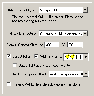
Add New Lights
If this checkbox is checkmarked then new lights will be added to the XAML file. The pre-defined light locations, color and light types are chosen from the following drop-down combo box.
- The first two icons represent the light type (Sun = directional light, Light bulb = point light, Spot light = spot).
- The second two squares represent the color of each of these two light sources.
- The text describes the location of the new light sources (see image below for visual locations).
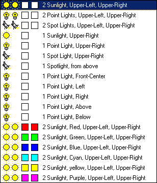
The new light sources will be placed according to the following image, along the XY plane. If you are looking down the Z axis (towards the negative Z axis) then upper-left will be (1), upper-right will be (3), lower-left will be (7) and lower-right will be (9).
Add New Lights Method
This combo box determines how the new lights are to be added to the exported XAML file.Merge with existing lights in the scene
This option will cause the newly chosen lights (from the drop-down combo box mentioned above) to be added to the already existing lights of the current 3D scene. In other words, all the lights of the current 3D scene will be output first, followed by the 1 or 2 new lights you have chosen from the drop-down visual list.Replace existing lights in the scene
This option will cause the newly chosen lights (from the drop-down combo box mentioned above) to be output to the XAML file, but no other light sources. None of the light sources in the original 3D scene will be output to the XAML file.Add new lights only if there are no existing lights in the scene
This option will cause the newly chosen lights (from the drop-down combo box mentioned above) to be output to the XAML file, but only if there are no existing lights in the original 3D scene. This is the default option. It will ensure that there are at least 1 or 2 new light sources added to the XAML scene if no lights exist in the original 3D scene.Preview XAML File in Default Viewer When Done
If this checkbox is checkmarked then the exported XAML file will be sent to the Windows Shell where it will start up your default XAML viewer to view the file. This option will only work if you have a XAML file viewer installed on your computer and it has been associated with the .xaml file extension.
This panel controls the output of entities to the XAML file.
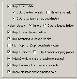
Output mesh data
If this checkbox is checkmarked then mesh geometry will be exported. This option also controls whether meshed versions of NURBS surfaces, bicubic patches, renderable NURBS curves or Spline Shapes will be output as well.Output vertex normals
If this checkbox is checkmarked then vertex normals will be exported along with the mesh geometry. Vertex normals are required to provide the "smoothing" information for a mesh model.XAML file sizes can be made smaller by disabling vertex normals, but the exported meshes will look "faceted".
Reverse Normals
If this checkbox is checkmarked then all vertex normals will be mirrored (inverted or reversed). You may want to try this option if the rendered XAML model looks unnaturally dark, or if the model appears inside out.See also the "Reverse orientation of all polygons" option on the Mesh Processing Options panel.
Output u,v texture map coordinates
If this checkbox is checkmarked then (u,v) vertex texture coordinates will be exported along with the mesh geometry. These are needed to define the mapping of 2D texture images onto the 3D mesh geometry. Disabling this option may result in smaller XAML files, but at the expense of not being able to map 2D texture images onto the mesh geometry.Hidden Objects Processing Mode
These two radio buttons determine how hidden objects in the scene are exported to XAML:Ignore
The objects are ignored and not output to the XAML file. This is the default method since it is compatible to all downstream XAML viewers and authoring programs.Output Flagged Hidden
This outputs the attribute tag "d:IsHidden=True" in the. This is only compatible (as far as we know) with Microsoft Expression Blend. The "d:IsHidden" is a new attribute tag defined via schemas included at the top of the XAML file and via the "mc:Ignorable=d" definition. NOTE: Inside Microsoft Expression Blend toggling the "hidden" flags will have no effect on the 3D objects seen on the user interface. The project has to be "Compiled" and executed for the hidden state to take effect.
Output hierarchy information
If this option is enabled (checkmarked) then the hierarchical relationship of objects in the scene will be exported using nested XAMLtags. If this option is disabled then no hierarchy will be output and all mesh objects will be exported in flattened worldspace coordinates. Pivot Points
Pivot points are a fundamental component of an animation system. In the realm of the PolyTrans animation system 'pivot points' define a local 3D coordinate system in space of an object about which the scale, rotation and translation animation function curves will be applied. The pivot point in PolyTrans is defined by a point in space and a local coordinate system defined by 3 orthogonal axes; the pivot point is defined relative to the local coordinate system of the mesh or geometry data.The following options specify how the PolyTrans pivot point information is exported to XAML:
Embed Pivot in All Geometry Data
The inverse pivot matrix (which defines the location and orientation of the pivot point) is multiplied into the raw mesh vertices. This is only done (and only necessary) when the parent null node is animated. This is the default option since it does not introduce any new anti-pivot nodes into the hierarchy tree.If it so happens that a PolyTrans null node (empty instance, empty folder) has animation on it as well as having a valid non-identity pivot matrix, then a child 'anti-pivot' node is added to the tree; the child node is assigned the inverse pivot matrix and the original parent transform node gets the animation data. This properly applies the anti-pivot effect to the subsequent children in the tree.
Output All Anti-Pivot Transform Nodes
A new 'anti-pivot' XAML dummy node is introduced into the hierarchy tree, between the mesh object and the parent XAML Transform node which has animation on it. The inverse of the PolyTrans pivot point matrix is assigned to the transformation matrix of this new anti-pivot node. This new anti-pivot node acts to 'pivot-in' the geometry vertices prior to the animation data being applied to the geometry.Don't Output Pivot Points (Ignore All Pivot Point Data)
This option prevents pivot point information from being output to the XAML file. Normally you would never want to enable this option.Use instancing to reduce file size
If this checkbox is checkmarked then the mechanism of "instancing" will be used to try and keep the size of the XAML file as small as possible. For example, if the source scene has 1000 bolts all derived from the same mesh primitive data, and the 1000 items have been placed in the Okino scene graph via "instancing" then during export to XAML only a single copy of the geometry mesh data will be exported to XAML, but with 1000 virtual copies made of it. These virtual copy instances merely act as indexes to the original mesh primitive data instead of being full copies, which can significantly reduce the size of the final output.
If this checkbox is disabled then unique and explicit copies of mesh data will be output to the XAML file regardless of whether each copy is exactly the same as previous copies already exported.
Flip "Y-Up" to "Z-Up" coordinate system
This option allows the default coordinate system to be set for the XAML file. It defines what will be considered the "Up" axis in the exported XAML file.Enabling this option (which is the default) will flip the source Y-up data of the internal Okino scene graph to the Z-up coordinate system of the exported XAML file.
Output Cameras
If this checkbox is checkmarked then all XAML parameters associated with the currently active perspective or orthographic camera definition will be output.Output camera clipping planes
If this checkbox is checkmarked then the "near" and "far" clipping plane values will be output to the XAML file for the currently active camera. This option is disabled by default since not all 3D source scenes have tight clipping planes computed for them.Indent XAML text (make readble formatting)
If this checkbox is checkmarked then tabs will be placed in the XAML file to make its hierarchical data structure evident. See the Example XAML 3D File section.If this checkbox is disabled then no indentation will be done on each line of the XAML file.
Output scene info in header comments
If this checkbox is checkmarked then cursory information will be output near the top of the XAML file embedded inside XML comments:<!-- Converted by Okino's PolyTrans XAML exporter. --> <!-- Date/time of export: 08/19/20XX 07:11:23 --> <!-- Bounding box of geometry = (-2,0,0) to (2,4,0). -->Report statistics about exported data
If this checkbox is checkmarked then statistics will be output after the XAML file has been exported, which looks like this:XAML Export statistics: Number of meshes = 1 Number of polygons = 2 Number of mesh vertices = 4 Number of vertex normals = 4 Number of uv texture coordinates = 4 Number of lights = 2 Number of directional lights = 2 Number of perspective cameras = 1 Number of materials = 1
Materials and texture maps are assigned to mesh objects in XAML files via material definitions. This panel controls the output of the material definitions, their associated texture maps, and provide fine grained control over the tweaking and modification of each XAML material property.
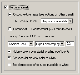
Output Materials
If this checkbox is checkmarked then materials will be exported to the XAML file.Material properties exported include:
- Ambient color
- Diffuse color
- Specular color
- Luminous color
- Opacity
- Phong shininess (power)
Output Texture Maps
If this checkbox is checkmarked then 2D texture maps that have been assigned to the material definition(s) will be exported to the XAML file.UV Scales & Offsets
Each texture map reference used in an Okino material allows for the texture map to be scaled and offset in "UV space". This combo box determines how this scale and offset information is output to the XAML file.Do not output (ignore)
The information is not output. You would normally not want to use this option since the applied textures will look wrong if any of them have scaling or offsetting.Output in material definition (default)
The texture's UV scale and offset values will be output inside theusing a "Transform" attribute. This is the default since it produces perfect export of this UV scale and offset information. Embed in uv texture coordinates of mesh geometry
The texture's UV scale and offset values will be embedded directly into the mesh's uv texture coordinates. If a mesh has diffuse, specular and luminous texture maps, all with different scale & offset values, then the scale and offset will only be taken from the diffuse texture map.Output XAML 'BackMaterial' (== 'FrontMaterial')
If this checkbox is checkmarked then a 'BackMaterial' will be output to the XAML file along with each front material reference. This is redundant because the front and back materials in Okino software are always the same.
Shading Coefficient and Colors Overrides
These combo boxes provide hands-on control over how exported material shading parameters should be modified so that the exported model can be rendered nicely as it would have looked in the source 3D program. The two combo boxes and the single numeric text box provide you good control over the ambient, diffuse, specular, luminous, opacity and shininess shading coefficients exported to XAML.The first drop-down combo box selects which of these shading parameters is to be modified. Each shading coefficient has its own operation that can be selected (via the second combo box) and an optional numeric text value (via the third data entry text input box). The following describes the various shading parameters that can be controlled:
Ambient Coefficient: This controls the amount of color reflected from an object based on the ambient light in a scene. A good default value is 0.1 through to 0.3 and ideally ranges from 0.0 to 1.0.
Diffuse Coefficient: This controls the amount of color reflected from an object based on the direct light shining on it. A good default value is 0.4 and ideally ranges from 0.0 to 1.0.
Specular Coefficient: This controls the intensity of the highlight color on an object. A good default value is 0.7 and ideally ranges from 0.0 to 5.0.
Luminous Coefficient: This controls how much color is added directly to an object, regardless of any light that shines on it (the higher the value, the more the object will appear to glow). In general this value should be kept at 0.
Opacity: This is the inverse of transparency. 0.0 will make the object fully transparent, while at 1.0 the object will be fully opaque.
Phong Shininess: This controls the width of the specular highlight seen on an object. An ideal range is 6 (very wide) to 300 (very narrow). The default is 32.
For each material shading parameter, several actions can be performed on each material shading parameter during the import process:
Do Not Export: When this option is selected, the shading parameter is set to 0, effectively making the shading channel appear black (for color channels).
Export Unchanged: When this option is selected, the shading parameter is exported as is, with no change.
Set and Use Default: When this option is selected, the shading parameter is set to some "good" default value (as determined by the export converter). This default value will be displayed in the input text box.
Set to Specific Value: When this option is selected, the exported shading parameter will be overridden with the user specified value of the numeric input text box.
Export and Crop by: When this option is selected, the shading parameter is exported and will remain unchanged if it is less than the numeric text input value shown on the dialog box. If it is greater, then the exported value will be clamped to be no greater than the numeric type-in value. This is a good operation, for example, if you do not wish for the ambient shading coefficient to be greater than 0.3.
Export and Scale by: When this option is selected, the shading parameter is exported and multiplied by the numeric input text value shown on the dialog box
Normalize Color and Coefficient: When this option is selected, this option only applies for the ambient, diffuse, specular and luminous shading coefficients and their respective RGB colors. This option is a hybrid approach that tries to automatically "guess" at a proper shading coefficient value given the raw (and corresponding) color imported from the file. As mentioned earlier, the shading coefficient is needed to create nice looking (nicely shaded) images in a photo-realistic rendering program. If this option is selected, then the specific shading coefficient will be derived directly from the relative intensity of the imported color that corresponds to this shading coefficient (diffuse color for diffuse shading coefficient etc.). For example, if the imported diffuse color is (0.4, 0, 0), which is 40% of full-bright red, then the diffuse shading coefficient will be set to 0.4 and the diffuse color will be modified to be (1, 0, 0). When the new color (1,0,0) and the new shading coefficient (0.4) ar multiplied together, it results in the original color imported from the file (0.4, 0, 0). In general you may wish to use the "Set and Use Default" option to get good rendered results.
Multiply Colors By Material Shading Coefficients
Inside Okino's internal scene graph each material has a "color" and a corresponding "shading coefficient" for each ambient, diffuse, specular and luminous color definition. The "shading coefficient" can be considered a variable intensity control that brightens or darkens its corresponding color, without having to modify the color itself.If this checkbox is checkmarked then each shading coefficient is multiplied into its corresponding color value before being exported to the XAML file material. Normally you would want this option enabled as it creates a XAML material definition which is very close in appearance to an Okino material definition.
If this checkbox is not checkmarked then only the raw colors will be output (ambient, diffuse, specular and luminous) to the XAML file and their corresponding shading coefficient values will be ignored. This will typically result in brighter, bolder and punchier materials, what we ourselves term "OpenGL" shading which tends to be more saturated than colors seen in photo-realistic rendering programs.
Set Diffuse Color of Textured Materials To White
This is one of those options that may come in handy for someone with particular requirements for their textured objects in the XAML file. It is patterned after a similar option from our OpenFlight export converter.
If this checkbox is checkmarked then any material which has a diffuse texture map assigned to it will be output in such a way that its diffuse surface color will be set to white. This is useful because certain realtime renderers use an "OpenGL" shading model in which the diffuse color is multiplied into the assigned texture map colors - if the diffuse material color is dark or black then the texture map will not be visible (often a problem when exporting from Maya for which the diffuse surface color is always set to black for textured materials). Enabling this option will cause the diffuse surface color to become white, and thus it will not affect the brightness of the assigned texture map.
If this checkbox is not checkmarked then the diffuse surface color will be exported unchanged.
NOTES:
- 3D objects in the XAML viewers will show up flat shaded unless there is a valid specular material color.
- This option is enabled by default since a white specular color if often perceived as the 'best' color for Phong specular highlights.
These options allow geometry processing, manipulation and optimization operations to be performed on the mesh data prior to export to XAML.
NOTE: These operations are performed on temporary copies of the mesh data and not on the original mesh data as contained internally within the Okino 3D scene graph. In other words, performing successive XAML file exports will not modify nor touch the original 3D scene data.
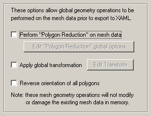
Perform "Polygon Reduction" on mesh data
If this checkbox is enabled (check-marked) then the XAML exporter will apply the global polygon reduction algorithm to each mesh object just prior to them being embedded in the XAML file.The algorithm allows the number of polygons in the scene to be greatly reduced. The parameters used to reduce the polygons can be modified by pressing the "Edit Polygon Reduction Global Options" button. Press the "Help" button on its corresponding dialog box to learn more about the polygon reduction system.
As described in the compression settings section of the Publish Panel documentation, it is often better to perform polygon reduction on your source dataset in order to create smaller XAML files rather than on relying on the Intel MultiRes compression algorithm used when the XAML file is created.
Apply global transformation
If this checkbox is enabled then a general purpose global transformation will be applied to each exported XAML scene. A new top-level grouping node will be added to the scene called "GlobalUserDefinedTransform" which will contain this new transformation matrix. All geometry, cameras and lights will be attached to this new XAML scene graph node unless you disable one of the respective "Affect Geometry", "Affect Cameras" or "Affect Lights" (disabling any one of these checkboxes will effectively prevent geometry, cameras and/or lights from being affected by the global transformation).This option will allow you to, for example,
- Re-center all of the geometry so that it is centered at the origin (0,0,0) in the XAML file.
- Move all of the geometry so that it is sitting on the Y=0 (XZ) horizontal plane.
- Auto-scale the geometry so that it is no larger than a specific bounding box size.
- Scale the scene by a (X, Y, Z) value.
- Shear the scene by a (X, Y, Z) value.
- Rotate the scene by a (X, Y, Z) value.
- Translate the scene by a (X, Y, Z) value.
Since the lights and cameras are attached to this new global transformation node, they will be affected along with the geometry.
The transformation can be edited by pressing the "Edit Transform" button which will cause the following global transformation dialog box to appear:
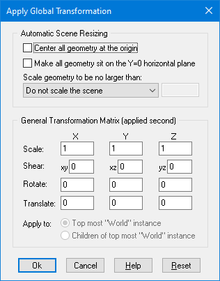
The transformation matrix will be computed in two phase: (1) the transformations specified in the top "Automatic Scene Resizing" section, then (2) the single transformation specified in the "General Transformation Matrix" section.
The values on the dialog box are described as follows:
Automatic Scene Resizing
Center all geometry at the origin
If this checkbox is enabled (checkmarked) then all the geometry data will be positioned so that it is centered about the origin. If disabled then the geometry will not be repositioned.Make all geometry sit on the Y=0 horizontal plane
If this checkbox is enabled (checkmarked) then the geometry will be repositioned so that it is sitting flush with the top of the Y plane (the horizontal plane).Scale geometry to be no larger than:
This option allows the geometry data to be automatically rescaled if it is too large. If set to 'Do not scale the geometry' then no scaling will be done. If set to '1x1x1 units' then all the objects will be scaled smaller should they exceed 1x1x1 units in total size. Likewise for the '2x2x2 units' option. If set to 'User defined maximum size' then the maximum size of all the objects can be set using the type-in numeric box. The default is '2x2x2 units'.Although not quite the same, if the option is set to Use Absolute Scaling Factor then all objects exported to the XAML file will be scaled absolutely by the user specified value. Thus, if you set the type-in value to 0.25 then all objects will be made 4 times smaller and if the value if set to 4 then all objects will be scaled 4 times larger. This is useful is you are converting a variety of different models to XAML format and you want them all uniformly scaled with the same scaling factor.
Transformation Matrix Values
Translate X, Y, Z
This applies a 3D translation by the specified amounts in the X, Y and Z dimensions.Scale X, Y, Z
This applies 3D scaling in the X, Y and Z dimensions. All 3 scale factors must be non-zero. Values above 1.0 will make the scene larger (2.0 will double the size of the scene) while values less than 0 will make the scene smaller (0.5 will half the size of the scene).Shear XY, XZ, YZ
This applies a linear shear in one of 3 directions:XY will shift all points in the X direction by the specified amount in proportion to the distance the points are located along the positive or negative Y axis. For example, using a value of 2.5 will shear all points by 68 degrees in the positive X direction; in other words, for every unit increase in the Y direction the X points will be shifted by 2.5 units.
XZ will shift all points in the X direction by the specified amount in proportion to the distance the points are located along the positive or negative Z axis.
YZ will shift all points in the Y direction by the specified amount in proportion to the distance the points are located along the positive or negative Z axis.
Rotate Around X Axis
Rotate Around Y Axis
Rotate Around Z AxisThis applies a rotation about the X, Y and/or Z axes. The rotation angle is restricted to the range -360 to 360 degrees. The angle of rotation is counter-clockwise when viewed from the positive to negative axis of rotation.Reverse orientation of all polygons
If this option is enabled (checkmarked) then the orientation of all polygons will be reversed, indirectly causing the vertex normals to also face in the opposite direction. For example, if the vertex normals of the object currently all face inward then this function will cause all of the vertex normals to face outward, and cause the orientation of each polygon to flip between clockwise and counter-clockwise.
This dialog box controls how referenced bitmap texture files will be handled during the XAML export process. These two options are basically:
1. Output a filename reference to a file on the local disk. Do not modify the bitmap filename reference and do not perform any bitmap conversion. This is useful if your bitmaps are already in a format recognized by the destination 3D program.
2. Same as #2 except that bitmap file format conversion is done under user control. A file reference will be added to the XAML file, and a new bitmap image of the desired file format, and with the desired bit depth and resolution will be created.
Texture Bitmap Handling Method (Combo Box)
This combo box determines the preferred method to output texture bitmap disk references:1) No Bitmap Conversion or Bitmap Filename Changes
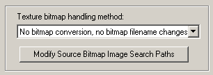
If this combo box option is seleced then:
- A reference to the texture image will be placed in the XAML file as a texture reference.
- The filename and file path to the texture image on disk will not be changed.
- The filename extension on the bitmap reference will not be changed.
- The path to the bitmap will not be changed.
- No automatic bitmap conversion will be performed.
2) Convert all Bitmap File References To Use New File Extension
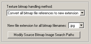
This is similar to option # 1 above, except that:
For example, if the option is set to TIFF then all bitmap filename references will be changed so that their file extensions end in .tif.
- The file reference placed in the XAML file will be changed such that its file extension is changed to that specified on the dialog box.
This is a useful option when all of the referenced texture maps have already been converted to this desired file format on disk.
3) Auto-Convert Bitmap Files to Another Format
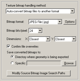
If this combo box option is chosen then all 2D bitmap images that are used by the current scene will be automatically tagged and converted into a new user-specified 2D bitmap file format on the local disk. The bitmap image will be written to the XAML file as a file reference and not as an embedded texture image.
For example, if the scene makes references to IFF bitmap files then this option can be selected so that the IFF images are automatically converted to the TIFF format.
If the bitmap texture(s) cannot be found in the location specified by the pathname prepended to the texture filename then the XAML exporter will search for the texture(s) in all directories specified in the file search paths (these can be modified by pressing the "Modify Source Bitmap Image Search Paths" button).
Bitmap File Format (Combo Box)
This combo box lists the desired destination bitmap file format that all texture bitmap images should be converted into.Bitmap Bits/Pixel: 2, 4, 8, 24 (Combo Box)
This combo lists determine the number of bits/pixel to write out to the new 2d bitmap file. The default is 24 bits. A color quantization algorithm will be used for the 2, 4 and 8 bits/pixel output formats. Not all bitmap file formats can accept 2-8 bits/pixel (e.g. in particular JPEG).Dimensions: X = #, Y = #
These two drop-down list boxes determine the X and Y resolution for the converted bitmap file(s).Confirm Potential Bitmap File Overwrites
If this checkbox is enabled (checkmarked) then the bitmap converter will confirm any potential overwrites of existing bitmap files on disk that have the same filename and extension as the one being written. If this option is disabled then no confirmation will be made.Save Converted Bitmaps To...
These radio buttons determine where the new bitmap file will be written to. Note that enabling the Replace all Bitmap File Paths With This Path: option or the Strip File Paths From All Bitmap References option from another panel will change the path prefix for the converted bitmap even though it was saved to disk in the location specified by one of these 3 radio button options.Directory Where Geometry Is Being Exported
The new bitmaps will be written to the directory where the exported files are being written to.Specific + Browse
The new bitmaps will be written to the directory specified by the input text edit box. This directory can be changed by pressing the Browse button.Modify Source Bitmap Image Search Paths
In specific circumstances it may be necessary to inform the XAML exporter where your source bitmap images are located so that automatic bitmap file conversion process or the image embedding process can locate and load the images.If the XAML exporter reports warnings that specific images could not be located during automatic bitmap conversion or embedding, then press this button so that the Search-Paths dialog box appears. Using this dialog box you can inform the XAML exporter where the source bitmaps are located.
If a texture bitmap file reference is to be added to a XAML file then this panel controls what will be done to the file path of that image filename.
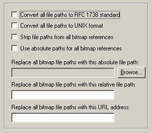
Convert all file paths to RFC1738 Standard
If this option is enabled (checkmarked) then all bitmap file paths written to the XAML file will be converted into the "RFC 1738" URL format specification. This option is rarely needed and is provided in this exporter for convenience.This option will override the "Convert all file paths to UNIX format" when enabled. However, the conversion to RFC1738 will not be done when a valid string is specified for the "Replace all Bitmap File Paths With This URL Address" option below (since it is assumed the URL address string specified is already in RFC1738 format). As examples:
C:\polytrans\bitmaps\texture.tif --> file:///C|/polytrans/bitmaps/texture.tif
\\machine\polytrans\bitmaps\texture.tif --> file:////machine/polytrans/bitmaps/texture.tif
Convert all file paths to UNIX format
If this option is enabled (checkmarked) then all bitmap file paths written to the file will be converted to a UNIX compatible format (it will not take effect if the "Convert all file paths to RFC1738 Standard" option is enabled). In particular, all DOS-specific backward slashes \ will be converted to UNIX forward slash / directory separators. Also, any DOS-like drive specifiers, such as c:\ will be removed from the file path and a warning message will be reported indicating the removal of this drive specifier (it should be ensured that all DOS-like drive specifiers are replaced by UNC specifiers, such as \\machine1\). If this option is disabled then no conversions will be made.Strip File Paths from All Bitmap References
If this option is enabled (checkmarked) then any file paths on a bitmap reference will be stripped off. For example, "C:\polytrans\bitmaps\texture.tif" will be output as "texture.tif".Replace all Bitmap File Paths With This Absolute File Path:
This option allows all exported bitmap references to be prefixed with a new filepath. This might be useful, for example, if all of the bitmap files are located in one specific directory or if you wish to change the prefix on the imported bitmap references. This new path will override all other options on this bitmap conversion dialog box (in other words, it will replace a bitmaps file path regardless of any other file path added to the bitmap via other options in this dialog box). To choose the filepath press the Browse button. To disable this option type any character into the "Replace all Bitmap File Paths With This URL Address" type-in edit box, then delete that character.Replace all Bitmap File Paths With This Relative File Path:
This is the same as the previous "Replace all Bitmap File Paths With This Absolute File Path" option except that it is possible to specify any arbitrary file path by typing the text into the type-in field. Whereas the previous method only allowed full qualified (absolute) file paths (ie: "C:\polytrans\bitmaps\texture.tif"), this option allows for relative file paths (ie: "bitmaps\texture.tif"). To disable this option, delete all text in the text input edit box.Replace all Bitmap File Paths With This URL Address:
If this option is enabled (checkmarked) then all bitmap filenames (used in association with a texture map) will be prefixed with the string specified in the URL input edit box. For example, if a texture references the filename:c:\files\textures\bitmap.tifwithin this programs database, and the URL is specified on this dialog box as:
http://www.okino.com/images/then the bitmap filename will be stored in the file as:
http://www.okino.com/images/bitmap.tif
This panel controls the export "animation conversion engine". This engine allows any form of source animation data to be exported cleanly and properly to XAML.
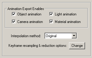
Object Animation
If this option is enabled (checkmarked) then object animation data which is currently contained within the internal database will be exported.Camera Animation
If this option is enabled (checkmarked) then camera animation data which is currently contained within the internal database will be exported.Preferred Interpolation method: Constant, Linear
This combo box determines which type of keyframe interpolation method should be used for the exported XAML file. At the moment the possible choices are constant and linear. In almost all cases you will want to use linear.Keep Original Interpolation Method When Possible
If this checkbox is enabled then the animation resampling process will attempt to preserve the interpolation method used in the original source animation data. This can often be accomplished, but not in all cases. When it can be accomplished, then the animation data sent to the XAML file will preserve the same interpolation type as the original source animation data. Otherwise, the animation output to XAML will use the "Preferred Interpolation Method" you have specified above. You will typically want to keep this checkbox enabled, unless you have specific reasons for wanting all your XAML animation controllers to use the same interpolation type.Preferred Rotation Type (Quaternion, XYZ, XZY, YXZ, YZX, ZXY, ZYX)
When we refer to the "rotation controller type" (or just rotation type), we are indicating whether a rotation animation is expressed in terms of Quaternions or in terms of Euler Angles. When rotation data is expressed in terms of Euler Angles, it is expressed in terms of some specific rotation axis order (such as XYZ or YZX). The rotation controller type of the original source animation data will have been chosen by the format-specific plugin which brought the source data into PolyTrans. Generally, the rotation controller type of the original source animation data could vary from object to object, from camera to camera, and from light to light.If and when animation resampling occurs on a rotation channel, the resampling process must select a target rotation type. Since repetitive-order Euler rotations (XYX, ZXZ, etc) of the source animation data are not entirely compatible with XAML's repetitive-order Euler rotations, it is sometimes necessary to pick an arbitrary rotation type as output for the resampling process. This arbitrary choice is left in your hands and is selected via this drop-down box.
Whenever the original rotation type can be replicated into XAML, you have a choice between keeping the original rotation type or always using one specific rotation type. That choice is controlled by the "Keep Original Rotation Controller Type When Possible" option below. If you disable that checkbox, then all rotation animation exported to XAML will be forced to use the rotation type selected in the "Preferred Rotation Type" list box.
Keep Original Rotation Controller Type When Possible
If this checkbox is enabled then the resampling process will attempt to preserve the rotation controller type used in the original source animation data. This can often be accomplished, but not in all cases. When it can be accomplished, then the rotation animation exported to XAML will use the same rotation controller type as the original source animation data. Otherwise, the rotation animation exported to XAML will use the "Preferred Rotation Type" as specified above. You will typically want to keep this checkbox enabled, unless you have specific reasons for wanting all your XAML rotation animations to use the same rotation type.NOTE: When this checkbox is enabled, rotation keyframe resampling might still occur. However, the resampled rotation keyframes will have the same rotation type as the original source animation data, when possible (or the "Preferred Rotation Type" when the original source animation data's rotation type is not compatible with XAML).
NOTE: The rotation type is not to be confused with the interpolation type. The selection of rotation type determines which rotation data channels are created for XAML (either a single Quaternion channel or 3 independent Euler Angle channels), as well as which Euler Angle order to use (when the rotation type is not Quaternion). Each rotation channel created for XAML must then be assigned an interpolation type, which is determined according to the relevant options above ("Preferred Interpolation Type" and "Keep Original Interpolation Type When Possible").
If this checkbox is disabled then the resampling process will use the "Preferred Rotation Method" you have specified above. If the original animation source data has a different rotation type, then resampling must occur. If the original source data has the same interpolation type as the "Preferred Rotation Method" you have specified above, then resampling will only occur if otherwise mandated.
Fix up -180/180 Degree Euler Flips (Maintain Euler Continuity)
This option fixes exported Euler rotation channels which flip back and forth between values close to 180 degrees and -180.0 degrees, from key to key. Normally this flipping will not pose a problem unless XAML "slows down" an animation for previewing in slow motion, and does sub-key interpolation (in such cases the objects may appear to randomly spin in the wrong direction at specific keys).This option can only take effect when rotation curves are explicitly resampled during the import process.
NOTE: This option will not take effect if the 'Preferred Rotation Type' is set to Quaternion and the 'Keep Original Rotation Controller Type When Possible' is disabled.
Background Info:
There are several cases where the exported rotation animation needs to be "resampled" from one mathematical format to another, such as if the Euler order has to be changed, or when quaternion animation needs to be cross converted to Euler animation curves for XAML.The resampling process first converts the rotation value(s) at each keyframe to a 4x4 rotation matrix, and then the matrix is decomposed into explicit (X, Y, Z) Euler rotation angles, of the desired Euler order. The Euler angles will always be in the range -180 to 180 degrees.
The primary disadvantage of the traditional Euler decomposition method comes about when the target program tries to view the animation in a "slow motion" mode. Since two adjacent frames might have values of, say, -179.9 and 179.9 (or vice versa) on one of the Euler angles, the sub-frame interpolation between these values will result in a quick spin through 359.8(!) degrees, rather than the intended 0.2 degree change. When a "slow motion" mode is not in effect, the user will traditionally never see the sub-frame interpolated values because the -179.9 and 179.9 rotations are absolute and correct values (needing no further interpolation between them).
Problem example: if the imported source rotations are 150.0 deg, 179.0, deg, 185.0 deg, 190.0 deg then after resampling the rotations will be 150.0 deg, 179.0 def, -175.0 deg, -170.0 deg. These are correct. However, some 3D viewers, during slow-motion playback where sub-frame interpolation is performed, will look at the 179.0 to -175.0 degree interval and create new interpolated values through a 354 degree rotation interval and not the shorter 6 degree rotation.
What This Option Does:
Enabling this option will allow an additional algorithm to be used which detects cases of "-180/180 degree Euler Flips" and attempts to fix them. This alternative algorithm will take the previous frame of animation into account when performing rotation resampling. It will attempt to decompose the rotation into a equivalent set of Euler angles which represents the smallest Euler-space change of values. This makes the algorithm very good for preventing -180/180 discontinuities in the Euler animation curves. This allows "slow motion" sub-frame interpolation to function as ideally expected.One possible down-side to this alternative algorithm is that Euler angles are free to "drift" away from the normal -180/180 range. Let us suppose you have an animation of a spinning top. Under the traditional algorithm, the top might spin from 0 to 180, then a discontinuity effect occurs, causing the next frames to go from -180 to 0 to 180, and so forth. With this option enabled, the top would spin from 0 to 180, then from 180 to 360 to 540, and so forth. There are hypothetical scenarios where users might not want that to happen. If that is the case, disable this option to ensure that all angles are clamped to the -180/180 range.
Resampling and Reduction Options
Pressing this button will show the animation resampling and reduction options dialog box. This, in general, controls the precision and reduction options used globally during animation resampling (for both import and export). If you find that your imported animation data looks jittery or does not hit target translations/rotations, then reduce the tolerance values.
If you disable keyframe reduction, then resampled animation data will have a key at every frame. You might have a specific reason to desire that output. Leaving keyframe reduction enabled, but setting the tolerance values to zero, will result in a curve which perfectly fits the original curve at all frames, but has all redundant keys eliminated. For example, if a channel is actually non-animated, then leaving keyframe reduction enabled with a zero tolerance will result in far fewer keys than entirely disabling keyframe reduction.