

| You are here: Home » Specialized Sections |
Support: 905-672-9328 Copyright © 2026 Okino Toronto, Ontario, Canada. |

Overview of the "Geometry Error Tolerance" Method.
Higher Quality Polygon Reduction for 2 or More Objects
![]()
![]()
![]()
A Quick Synopsis
The Geometric Error Tolerance Reduction Method is a special mode, and technique, of the Okino polygon reduction system which can often result in upwards of 95% to 98% or even 99% reduction on many CAD datasets, with little degradation in the final model's quality. It focuses on reducing a model's polygonal complexity until a specific, fixed and absolute mathematical "error tolerance" is exceeded for each object rather than trying to blindly reduce the entire model to a fixed number of user-requested polygons. As such, it is an iterative process and not a quick "push button" process.
A Quick 'How To Use' the Geometric Error Tolerance Reduction Method
1. Set the "Percentage of Model to Remove via Reduction" slider on the first panel to your desired and ideal reduction amount, such as from 85% to 100%.
2. Press the 'Reduce!' button.
3. Exit the polygon reduction dialog box and then press Control-Z to undo the last reduction operation. The reduced model will most likely not look too good at this point in the reduction process.
4. Start up the polygon reduction system again.
5. Examine the minimum and maximum "geometric errors" shown at the top of the "Geo Tolerance Reduction" panel. You will need to enter an educated guess into the Geometric Error Tolerance type-in value. A good starting value is a number closer to that of the 'minimum geometric error' value. After 2 to 5 iterations, and based on more experience, you'll come to guess these numbers more quickly. Note:Higher error tolerance values = more reduction (more polygons will be removed).
6. Press the 'Reduce!' button once again and exit the polygon reduction dialog box. Examine your model for quality. If you do not like the quality of the model then press Control-Z until the model has reverted to its original non-reduced version (or, just re-load the model back in from disk, preferably from an Okino .bdf scene snapshot file).
7. You will need to repeat actions (4) through (6) until you are arrive at your optimal reduction. You may want to increase/decrease the guessed Geometric Error Tolerance value by a factor of 10 to converge on the most optimal model. For example, we may start at 0.001 and increase our guesses to 0.01, 0.1, 1.0 and higher until we achieve our desired level of reduction and model quality.
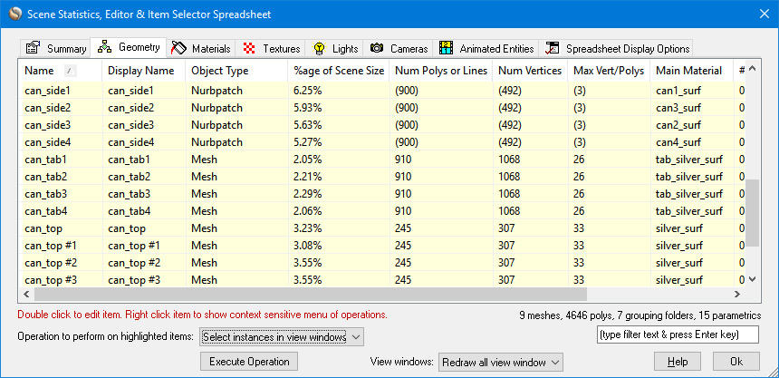
As another suggestion, you will want to examine your model via the scene spreadsheet editor (Control-E from the keyboard) before, during and after the polygon reduction process. The editor will point out which areas of the model are consuming the most polygonal data and hence which areas of the model may need more selective reduction. Also, in many cases, it is best to just delete some objects which (1) use up a lot of polygons and (2) which are not visible to the viewer.
Basic Explanation:
There are two primary methods by which you can control the final number of polygons removed from a model:
§ Using the "Percentage of Model to Remove via Reduction" slider on the main options panel,
§ And/or the "Geometric Error Tolerance" type-in value.
During each iteration of the reduction algorithm every possible edge contraction of a model is stored in a heap in order of increasing error. At each iteration the edge contraction at the top of the heap is performed (the edge contraction with the lowest possible error). The polygon reduction algorithm will thus stop when one of the following two conditions is met:
1. The total number of polygons removed from the object is equal to or exceeds the "Percentage of model to remove via reduction" slider on the main dialog box options panel.
2. Or, the geometric error of the top-most edge contraction in the heap exceeds the user entered value specified by the "Geometric Error Tolerance".
Thus, there are two methods to have the polygon reduction algorithm stop: either when the specified percentage of polygons is removed, or when all of the available contractions have exceeded the error specified by the "Geometric Error Tolerance".
The advantages and disadvantages of both stop criteria are outlined here:
1. If you are reducing multiple objects at the same time, method # 1 will remove a fixed percentage of polygons from each model irrespective of the quality degradation in the other models. This does not work well when there are some models with 100 polygons and others with 100,000 polygons in them; we would like the low polygon count models to retain the most detail while removing the most polygons from the high polygon count models -- however, this does not occur since each model gets the same fixed percentage of reduction. The advantage of method # 1 is that it is a quick and easy user control to select the final reduction amount (one slider), and works just as well as method # 2 when all the objects are temporarily moved into a single object for polygon reduction.
2. In method # 2 (error tolerance based), the reduction stops based on the global maximum allowable geometry error per object, not on a fixed amount of reduction. This means that a 100 polygon count model may retain most of its polygons while a 100,000 polygon count model will lose the most polygons. The advantage is a more uniform reduction amongst all separate models in the scene (see below for example). The main disadvantage is that you have to selectively guess at an appropriate number to enter for the "Geometric Error Tolerance" type-in value in order to achieve the desired percentage of polygon reduction.
The following mini tutorial will explain how to "guess" at a good value to use for the "Geometric Error Tolerance" parameter, often leading to better quality results than if the percentage slider value is chosen only. By setting the maximum geometric error level appropriately you may end up with better looking scenes, because polygons will be removed more selectively amongst multiple models, in particular from objects that are very small and insignificant, have an overly high density of polygons, or low curvature. Conversely, objects that already have an efficient distribution of polygons will not be oversimplified.
Simple Example: 3 Spheres
This simple example will clearly show you the advantage of using method #2, setting the "Geometric Error Tolerance" parameter.
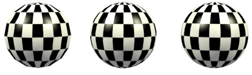
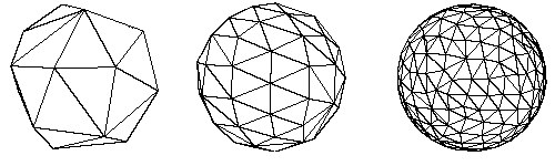
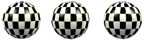
Our initial scene is 3 spheres of increasing density, 128, 450 and 1800 polygons:

Let's apply 85% polygon reduction to all 3 spheres at the same time, without moving them into a single object:
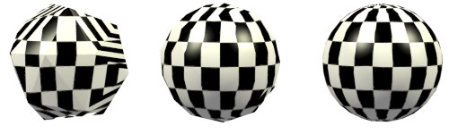
This illustrates the basic problem we mentioned above: each model (sphere) is being reduced based on a fixed percentage of polygons, irrespective of the quality of the other models. Each sphere is being sent through the polygon reducer one by one. The result is that the left-most sphere has too little detail (chunky) and the right-most sphere has too much detail.
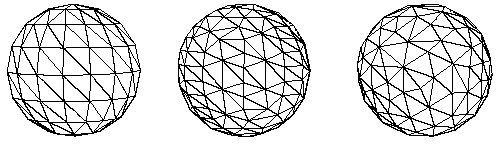
The ideal method to reduce a scene is to move all objects to a single object, perform the polygon reduction and explode the resulting scene into multiple objects again based on their material assignments. This is ideal because the amount of reduction is performed uniformly across the single (new) object instead of individually for each model. Let's try this before we venture to method # 2 (the objective of this tutorial). In the following images we have moved all 3 spheres into a single object (by selecting them and executing the "Move Selected Objects To New Object" menu command) and performing polygon reduction at 85% resulting in 640 polygons.
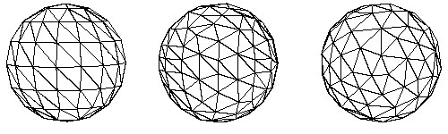
You will notice that all three spheres now have a uniform density of polygons. This is what we want to achieve. However, we can no longer break them apart into their original object definitions because all 3 spheres originally were assigned the same material assignment. This single-object method is still very good, and recommended, but you have to assign different materials to the objects if you wish to explode them again after the polygon reduction has finished.
Now, let's venture on to the central point of this tutorial: using the "Geometric Error Tolerance" type-in value to reduce all 3 spheres one by one (without moving them into a single object) but still result in the same uniform density of polygons as we saw in the last set of images above. The final scene will still be 3 separate spheres, in their original hierarchy location, and with a nice uniform reduction per object.
§ Action 1: If you haven't done so yet, save your scene to disk using the Okino .bdf save file format. Start the polygon reduction algorithm in the normal method to reduce all or multiple objects at the same time. Press the 'Reset' button on the first polygon reduction options panel and then set the "Percentage of model to remove via reduction" slider to the approximate number of polygons you want to remove. We'll set it to 85%. Press the "Reduce!" button to perform our first test reduction.
§ Action 2: Look at the "Geo Tolerance Reduction" dialog box panel and take note of the "Minimum geometric error from last reduction execution" and "Maximum geometric error from last reduction execution". These describe the minimum and maximum geometric errors encountered for all 3 spheres while they were being reduced one by one. These are the "magic helper numbers" that will tell us how to guess an appropriate value for the "Geometric Error Tolerance" type-in value. For our 3 sphere the min/max values are 0.000165 and 0.05625.
§ Action 3: Exit the polygon reduction dialog box and then press Control-Z to Undo the previous polygon reduction operation, or reload the original Okino .bdf scene file from disk. Start up the polygon reduction dialog box again and this time set the "Percentage of model to remove via reduction" slider to 100% (we don't want it to affect our final reduction amount). Next, (and the magic part) type in a new number to the "Geometric Error Tolerance" type-in value. This number has to be somewhere between the minimum and maximum error values reported from the last reduction execution, as taken note in action # 2. You will want to select a value much closer to the minimum reported value than the maximum reported value. If we use the minimum error value as a starting point then we probably won't achieve your desired level of reduction, so start at a higher value. For huge scenes with large and small parts we typically use a value 2/3rds the way between the minimum and maximum values, but for these simple spheres we will try a value a starting value 3 times larger than the minimum found in action #2, roughly 0.0006 (we don't need a perfectly accurate number; any approximate number will do). If we re-run the algorithm we end up with 84% reduction total amongst all three spheres, as shown here:
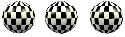
We were very lucky on our first attempt to select the magic number (max. error tolerance) which would result in the ideal percentage reduction we are looking for (85%). Notice that all three spheres show a uniform polygon density even though they were reduced individually. The other advantage is that the resulting spheres are still 3 separate objects and do not need to be exploded back into separate pieces as method # 1 requires.
§ Action 4a: If the last reduction of action # 3 resulted in too little percentage reduction then increase the "Geometric Error Tolerance" value and repeat action # 3 (press Control-Z to Undo the previous polygon reduction operation or reload the original Okino .bdf scene file, enter a new value, Reduce!, examine final percentage reduction, repeat until happy with final reduction amount). We find that it might take 3 to 5 attempts to narrow down an ideal value for this type-in value. On the second attempt you might want to try a number 2x, 5x or 10x larger.
§ Action 4b: If the last reduction of action # 3 resulted in too much percentage reduction then decrease the "Geometric Error Tolerance" value and repeat action # 3. If the last attempt, for example, increased this value 10x then try using a value only 2x larger on the next attempt. Repeat action # 3 using different values until you finally converge on the desired level of polygon reduction.
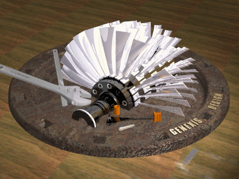
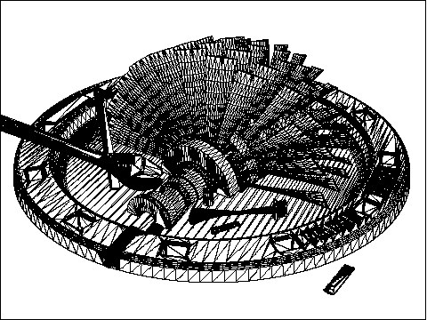
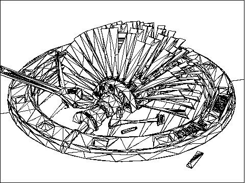
Complex Model Example: The Genexis Design Turbine-on-a-Plate
In this short sub-tutorial we will apply the 4 acitons outlined above to a real-world complex CAD model that has 89 parts, 123276 polygons, and a complex tree hierarchy. It is the conceptual "Turbine Blades on a Plate" scene created by Genexis Design of Toronto. For this example we wish to reduce the overall model by 96%, as individual pieces and not have to resort to converting to a single model prior to perform reduction. As such, we will need to find an ideal value for the "Geometric Error Tolerance" type-in value so that each individual component of the scene is reduced to an ideal error amount. Since this scene is ray traced with many inter-reflections amongst the blades, we want to greatly reduce the number of polygons to speed up the rendering process.
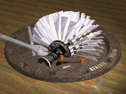
The original scene (123276 polygons) takes 3:44min to render using 60MB of memory:
Action 1: Initially we set the "Percentage of model to remove via reduction" slider to 96% and reduce the model using default parameters. This results in "Minimum geometric error from last reduction execution" and "Maximum geometric error from last reduction execution" values of 0.000008 and 2286.042. Quite an extreme range!
** NOTE ** For very large models you will probably not be able to run the reduction algorithm on the entire model to determine these min/max geometric error values. In these cases select 3 or so distinct objects from the multi-part model and perform polygon reduction on only these 3 objects at the same time. These 3 objects most probably will represent the overall min/max geometric error for the whole model. You can then proceed to action 2 using these approximated min/max values.
Action 2: The model is reloaded (or Control-Z pressed to Undo the previous polygon reduction action), the "Percentage of model to remove via reduction" slider set to 100% and the "Geometric Error Tolerance" type-in value set to an arbitrary starting value of 0.0001.
Action 3: The reduction algorithm is run again. This results in an overall scene polygon reduction of 87%. The 16453 triangles now takes 1:56min to render and only 13.4MB of memory:
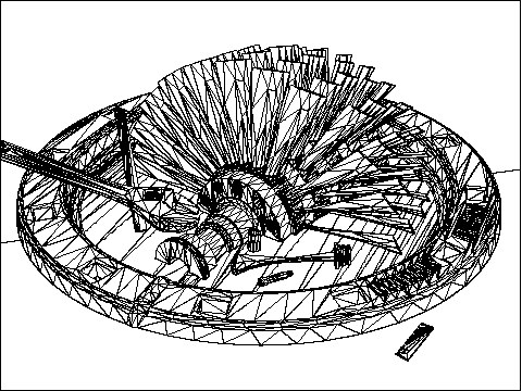
Action 4: If we reload the scene (or press Control-Z to Undo the previous polygon reduction action), increase the "Geometric Error Tolerance" type-in value to 0.001 and run the reducer again then we achieve a 95% polygon reduction -- our target goal. These 6692 polygons now render in 1:41min and with 9.5MB of memory:
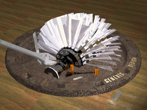
Note how similar this image is to our original un-reduced scene rendering! They are nearly identical even though this latter scene contains 95% less polygons (6692 vs. 123276 polygons). This is an ideal example of how polygon reduction can best be applied to CAD data to reduce rendering time of a complex scene.
Final Synopsis of this Tutorial
This tutorial has basically described the key differences between using the "Percentage of model to remove via reduction" slider and the "Geometric Error Tolerance" type-in value to control the final degree of polygon reduction. The latter type-in value is an ideal method to produce high quality reductions when it is not possible to squeeze all objects into a single object prior to reduction.