| You are here: Home » Import CAD Formats » NGRAIN's 3KO Solutions |
|
Please also refer to the corresponding Okino DirectX importer.
The DirectX geometry export converter for Okino's PolyTrans program writes out complete 3d scene databases in a highly robust and professionally guaranteed manner to Microsoft's 'Direct 3D' file format, including all mesh data (vertex normals, vertex colors, uv texture coordinates), hierarchy, texture references, automatic conversion of foreign bitmaps, skin weights exported from select source programs (real time deformation of single skin meshes by skeletons), as well as vertex duplication lists. Object animation conversion, resampling and capture from 3ds Max, CINEMA 4D, Maya, LightWave, U3D, Collada, FBX, etc. to DirectX is a critical and key feature of the DirectX exporter.
As Okino was the first company to proactively develop a DirectX converter in cooperation with Microsoft, we personally guarantee professional conversions from all main source programs, most importantly all animation and skinned mesh conversions such as from 3ds Max and Maya. DirectX is a notorious file format and playback engine with unpublished quirks, and Okino has overcome all these quirks as part of the conversion process. This exporter has been bug free and stable for well over a decade, being in use by every major DirectX professional 3D user, production studio and game studio during that time. It is totally supported by Okino from its origins to today.
This DirectX export file converter is a complete implementation of the DirectX file format specification. It also overcomes all the hard problems associated with DirectX files such as splitting welded vertices into two unique vertices so that proper texture mapping can be applied.
The main features include:
- Proper translation of all forms of geometry into the DirectX 'Mesh' primitive, complete with support for the 'MeshNormals', 'MeshMaterialList', 'MeshVertexColors', 'MeshTextureCoords' and 'FvFData'.
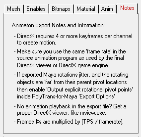
- Guaranteed animation conversion from all major source animation systems -- that is our core business and competency in the DCC/animation market. DirectX needs at least 4 keys per animation curve to ensure proper playback.
- Flexible freedom to export named "animation sets", each with a different start and end frame. This is useful for creating animation cycles and walks, segmented from a single timeline.
- Export of skin weights, from select source programs, for realtime deformation of single skin meshes by their associated bound skeletons (the skeletons are represented as frame hierarchies). All known DirectX skinning conversion quirks are automatically handled by the exporter. Okino has dedicated more than a dozen man years in its animation and skinning conversion systems, so we completely know how to make this happen for customers.
- Export of vertex duplication lists. In order to output proper uv texture coordinates there are cases when vertices of a mesh have to be duplicated. The vertex duplication list allows the reader of the .X file to undo this duplication process.
- Object hierarchy support by embedding mesh data within a 'Frame' structure.
- Automatic conversion of bitmap files to all major 2D bitmap file formats. Also, the converter can resize the bitmaps so that they are a power-of-two and square in size.
- Conversion of DirectX HLSL shader references and their related runtime parameters from 3ds Max into equivalent DirectX "EffectInstance" file references.
- The converter can take any arbitrary 3D object (including those with n-sided polygons and optional holes, bicubic patches or NURBS patches) and convert them to optimized triangle meshes.
- Since the DirectX file format does not allow for scale and offset values for each texture bitmap (as is provided by most rendering program’s material definitions), this converter incorporates a smart routine which adds redundant vertices to a polygon mesh and directly multiplies in the scale/offset values into the (u,v) texture coordinates.

File Type = ASCII, Binary
If the radio button is set to 'Binary' then the .X file will be written in the binary file format. If set to 'ASCII' then the .X file will be written in the ASCII file format.Reverse Orientation of all Polygons
If this option is enabled (checkmarked) then the orientation of all polygons will be reversed (the winding order of the faces will be reversed). This will effectively reverse the direction of each polygon's geometric normal.Flip Polygon Normals
If this option is enabled (checkmarked) then the direction of each vertex normal (if any normals are output) will be flipped so that they point in the opposite direction. This option should be enabled if the shading looks wrong on the exported objects.Output All Data As a Single Mesh Object
If this option is disabled (un-checkmarked), which is the default, then the converter will output one or more 'Mesh' structures per file, each corresponding to an object within the 3d database.If this option is enabled (checkmarked) then the converter will output all object data to a single ‘Mesh’ structure. Note that enabling this option implies that the ‘Encapsulate Mesh Data in ‘Frame’ Hierarchy’ and the ‘Output Transformation Matrices With Each Frame’ options are disabled.
Allow Vertex Geometry Alteration for (u,v) Texture Coordinates
Due to a limitation of the DirectX file format polygon vertices have to be duplicated in order to properly output the (u,v) texture coordinates. For example, if a corner of two abutting polygons share the same vertex coordinate but have two different (u,v) coordinates then this vertex coordinate will have to be duplicated two in the exported DirectX file.If this option is enabled (checkmarked) then the converter will properly output (u,v) texture coordinates by duplicating (altering) the vertex coordinate data. If this option is disabled (un-checkmarked) then the converter will not alter the vertex coordinates and thus the (u,v) texture coordinate may or may not be output properly.
NOTE: The destination program can undo this vertex duplication by way of the "VertexDuplicationIndices" which can be exported to the .X file when the "Output vertex duplication list" option is enabled. This is a new option for DirectX 8.
Output All Polygons As Triangles
If this option is enabled (checkmarked) then all polygons which have 4 or more sides will be converted to triangles prior to output. Concave polygons and polygons with holes will be properly triangulated.Encapsulate Mesh Data in 'Frame' Hierarchy
If this option is enabled (checkmarked) then the converter will recreate geometry hierarchy in the .X file by embedding each mesh structure within one or more layered 'Frame' structures. Such a file should be loaded into Direct3D using the 'Frame::Load' command.If this checkbox is disabled then no 'Frame' or 'FrameTransformMatrix' structures will be output. Such a file should be loaded into Direct3D using the 'Mesh::Load' command.
Output Transformation Matrices With Each Frame
If this option is enabled (checkmarked) as well as the 'Encapsulate Mesh Data in 'Frame' Hierarchy' option (explained above) then each mesh structure will be preceeded by a transformation matrix which will transform the data from the coordinate system of it's parent frame to the coordinate system of the mesh's local frame.If this option or the 'Encapsulate Mesh Data in 'Frame' Hierarchy' option is disabled then all transformation matrices will be multiplied directly into the vertex coordinates of each mesh and no matrices will be output to the file.
Convert and Output Animation Data
If this option is enabled (checkmarked) then animation data will be output to the .X file. Such a file should be loaded into Direct3D using the 'AnimationSet::Load' command. Only a specific number of supported import formats can output animation data to the DirectX file. The program will optimize the data to remove redundant keyframes. This animation export capability is only available when running this export converter with Okino's PolyTrans or NuGraf Rendering System software.Note that enabling this option implies that the Encapsulate Mesh Data in Frame Hierarchy and the 'Output Transformation Matrices With Each Frame' options are enabled and that the ‘Output All Data As a Single Mesh Object’ option is disabled.
Method to Convert from Right-Handed Coordinate System to Left-Handed Coordinates
DirectX uses a left handed coordinate system whereas PolyTrans/NuGraf use a right handed coordinate system (as is common for most 3D file formats, except for Lightwave which is left handed as well). This drop-down box selects which method will be used during export to change from right-handed coordinates to left-handed coordinates.
Don't Do Anything
As its name implies, nothing is done to the exported data. In this case you may find that the exported scene looks incorrectly mirrored about the XY plane and that rotations are in the wrong direction.
Flip Z of Vectors and Reverse Angle of Quaternions
This is the most ideal option to enable, but not the default at this time. This option causes the Z coordinate of all vectors to be negated and the angle of all quaternion rotations to be reversed.
Flip Z of Top-Level Matrix
This option simply applies a -1 scale vector in Z to the top-level frame matrix in the file. This basically mirrors the entire scene about the XY plane. This works well except for custom programs which import .X files and expect that all coordinates and matrix frames be in LHCS; for the latter case go and enable the "Flip Z of Vectors and Reverse Angle of Quaternions" option.
'World' Scaling Factor
This number allows the exported geometry data to be scaled in size. Values less than 1.0 will make the 'world' smaller while values greater than 1.0 will make the 'world' larger. If after loading a .X file into a .X file viewer you cannot see anything then try a scale value of 0.1, 0.01, 0.001, etc.Line Terminator Type
This common option selects which line terminator is to be used for the ASCII output file:
- Files destined for DOS/PC machines should use CR/LF,
- Files for UNIX machines should use LF, and
- Files for Macintosh machines should use CR.
The default is specific to which machine this converter is presently running on: CRLF for DOS/PC, LF for UNIX and CR for Macintosh. This option normally does not have to be specified unless you will be using the exported ASCII file on a different type of computer.
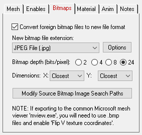
Convert Foreign Bitmap Files to New File Format
If this checkbox is enabled then all 2d bitmap textures which are currently defined and referenced by the internal NuGraf/PolyTrans database scene will be automatically tagged then converted to a new user-specified 2d bitmap file format during export. The desired format is chosen using the Bitmap File Format combo box. If the texture(s) cannot be found in the location specified by the pathname prepended to the input texture filename then the export converter will search for the texture(s) in all directories specified in the 'Default Search Path' and the 'Texture Bitmaps Search Path' file search paths (these can be modified by choosing the 'Preferences/Configure File Search Paths' menu item.Bitmap File Format (Combo Box)
This combo box lists the destination bitmap file format.Bitmap Depth (Bits/Pixel): 2, 4, 8, 24
These radio buttons determine the number of bits/pixel to write out to the .bmp texture file (.ppm files are always 24 bits). The default is 24 bits. A color quantization algorithm will be used for the 2, 4 and 8 bits/pixel output formats.Dimensions: X = #, Y = #
If the 'Convert Bitmap Files to .bmp or .ppm Format' option is enabled then the following two drop-down list boxes determine the X and Y resolution for the converted bitmap file(s):
No Change = Do not change the X or Y size Closest = Use the next highest power-of-2 size 2, 4, 8, ... 256, 512 = Choose a specific size for the X or Y dimension All texture bitmap images used by Direct3D must be a power-of-2 in size (2, 4, 8, 16, etc.).
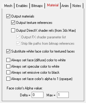
Output Materials
If this option is enabled (checkmarked) then any material attributes assigned to individual polygons will be output to the .X file using the 'MeshMaterialList' structure.Output Texture References
If this option is enabled (checkmarked) then any material which uses a bitmap texture will output a reference to the texture map using the 'TextureFilename' command.Output DirectX shader refs (from 3ds Max)
These series of options are specialized for use with 3ds Max and any objects which have been assigned a "DirectX HLSL Shader". Enabling this checkbox will pass-through DirectX HLSL shader references ("FX" file references) from a 3ds Max scene into the DirectX file as "EffectInstance" references.Basic requirements:
You must be exporting to the DirectX file format from within 3ds Max and using PolyTrans-for-3dsMax. The 3ds Max material(s) must have had the "DirectX Shader" assigned. NOTES:
The basic DirectX material properties (diffuse/specular/emissive colors and opacity) and the name of the DirectX material will come from the "Software Render Style" material (the sub-material associated with the DirectX shader). As a general note of interest, the FX shader information is passed from 3ds Max through Okino software via metadata assigned to each exported material definition. Output FX shader parameter list
If this option is enabled (checkmarked) then the parameter list associated with a FX file will also be output to the DirectX file, as shown below:Material StandardFX_renderstyle__sub_ { 0.588000;0.588000;0.588000;1.000000;; 3.000000; 0.000000;0.000000;0.000000;; 0.000000;0.000000;0.000000;; EffectInstance { "StandardFX.fx"; EffectParamFloats { "k_a"; 4; 0.000000, 0.000000, 0.000000, 1.000000; } EffectParamDWord { "n"; 15; } EffectParamDWord { "g_AlphaVertex"; 1; } EffectParamString { "Tex0"; "tiger.bmp"; } } }Strip file paths from bitmap references
If this option is enabled (checkmarked) then any absolute file path associated with FX file bitmap references will be stripped off, otherwise they will be output verbatim. As two contrary examples:EffectInstance { "colortest.fx"; } EffectInstance { "c:\\fx_files\\colortest.fx"; }NOTE: The Convert All File Paths To Use Forward Slashes option on the Enables panel also controls whether the directory path slashes will be output as forward or backward slashes.
Substitute White Face Color For Textured Faces
When texture mapping a polygon Direct3D first multiplies the polygon's face color (the diffuse color) by the texture pixel value. This has the unfortunate side effect of tinting the texture mapped surface and/or making it darker. For example, if the current face color is black then the polygon will appear black; if the current face color is blue then the texture mapped polygon will be tinted blue.If this option is enabled (checkmarked) then the face color for a polygon will be set to white whenever that polygon has a texture map applied to it. This will ensure that the texture mapped surface does not become tinted and/or darker.
If this option is diabled (un-checkmarked) then the face color will reflect its true color as exported from the database (it will not be changed to white).
Always Set Face (Diffuse) Color to White
If this option is enabled (checkmarked) then the face color (diffuse color) will always be output as white (1,1,1).Always Set Specular Color to White
If this option is enabled (checkmarked) then the specular color will always be output as white (1,1,1). The specular color controls the color and intensity of the specular highlight.Always Set Emissive Color to Black
If this option is enabled (checkmarked) then the emissive material color will always be output as black (0,0,0).Always Set Face's Alpha Value to 1 (Completely Opaque)
If this option is enabled (checkmarked) then the face color's alpha value will always be output as 1.0 (completely opaque).Face Alpha Color Change
These two parameters allow the alpha value of the face material color (diffuse color) to be modified. If the current alpha value is less than the 'Max' parameter then the 'Delta' value will be added to it, else the alpha value will not be modified. For example, if the alpha value is 0.3, the 'Delta' value is 0.4 and the 'Max' value is 1.0 then the export converter will add 0.4 to 0.3 and output the alpha value as 0.7; however, if the 'Max' value was set to 0.2 then nothing would change since the alpha value (of 0.3) is not less than the 'Max' value.
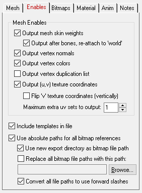
The check boxes inside the 'Output Enables' section control what type of data will be output to the .x file:
Output Mesh Skin Weights
"Mesh skinning" is the process of deforming a single skin mesh with a skeleton (in the .X file the skeleton is represented by the frame matrices which define the pivot point and orientation of each invisible bone). The contribution of each bone of the skeleton to the deformation of a vertex in the mesh is controlled by vertex weights. If this option is enabled then a mesh will be bound to one of more "frames" in the .X file (which represent the bones or joints of the skeleton) via transformation matrices and weight values. This option is only valid if the source data has at least one mesh object bound to any number of other objects, null nodes or skeleton nodes in the scene (any object can be a deformer).Output Skinned Meshes After Bones Have Been Output, and Re-attach to "World" Frame
Skinning works by having a mesh object reference one or more "bone" controlling objects in the scene. For DirectX these "bones" are just the transformation matrix of a frame. The ideal situation is to have the bone nodes (transform nodes) output first and then the skinned mesh last, since the skinned mesh makes references to the previously output bone node names. If this option is enabled (which is the default) then a two pass method will be used; in the first pass all the hierarchy, the transform nodes (including those which act as bones) and non-skinned meshes will be output. In the second pass the skinned meshes will be output, except this time they will be re-attached in the hierarchy to the "world" root node and not be inserted anywhere in the hierarchy. This latter stage of reconnecting the skinned meshes to the "world" is fine because their location in the hierarchy does not matter at all (during skinning only the location and animation of the "skeleton of bones" actually deform and move the skinned mesh into its final deformed state and location). If this option is disabled then the skinned meshes will be output in their normal hierarchy location.Vertex Normals
If this option is enabled (checkmarked) then any normals that are assigned to polygon vertices will be output to the X file using the 'MeshNormals' structure.Vertex Colors
If this option is enabled (checkmarked) then any colors that are assigned to polygon vertices will be output to the X file using the 'MeshVertexColors' structure.Vertex Duplication List
DirectX8 introduced a new template called a vertex duplication list. It specifies which vertices in a mesh had to be duplicated during the export process due to different adjacent materials at a polygon boundary. By using this list during import in the destination program the vertex duplication phase can be undone very easily.Textures Coordinates
If this option is enabled (checkmarked) then any (u,v) texture coordinates that are assigned to polygon vertices will be output to the .X file using the 'MeshTextureCoords' structure.Flip 'v' Texture Coordinates (vertically)
If this option is enabled (checkmarked) then all 'v' texture mapping coordinates will be flipped (inverted) so that the texture maps will appear inverted when rendered using DirectX. It has been reported that DirectX versions 2.0 through 3.0 had a bug in them such that all texture maps were incorrectly inverted. Thus, models that appear correct in v2.0-v3.0 will appear inverted if rendered within newer versions of DirectX (such as v5.0). To solve this problem, simply enable this option for models exported to DirectX v5.0 or newer if the texture maps appear flipped vertically.Include Templates in File
If this option is enabled (checkmarked) then 'templates' will be output to the .X file. This is the default.Use Absolute Paths For All Bitmap References
Inside a DirectX file a 2d bitmap texture can be applied to a material using the “TextureFilename” command whose argument is a filename to a BMP or PPM formatted bitmap image. If this option is enabled (checkmarked) then the filename will also include a complete file path to the file’s location (ie: “c:\images\carpet.bmp”). If this option is disabled (un-checkmarked) then no file path will prefix the filename (ie: “carpet.bmp” will be output).Use New Export Directory As Bitmap File Path
If this option is enabled, and the ' Use Absolute Paths For All Bitmap References' option is enabled, then the texture map filename exported to the DirectX file will will be prepended with the same filepath as the directory where the DirectX file is being exported to. For example, if you are saving the new DirectX file to directory "c:\myfiles" then an exported texture filename will look like "c:\myfiles\carpet.bmp". If this option is disabled then NOTHING will be done to the exported bitmap filename. This is ideal if you have imported some 3D file which uses absolute texture filepaths and you wish to have these exact same filepaths exported to the DirectX file. So, if you imported a file with a filepath named "c:\texturesfiles\carpet.bmp" it will be exported to the DirectX file exactly the same with no changes.Convert All File Paths To Use Forward Slashes
If this option is enabled (checkmarked) then all file paths on the bitmap filenames will use forward slash separators (ie: '/images/directx/brick.bmp') whereas if this option is un-checkmarked then the bitmap filenames will use backward slashes (ie: '\images\directx\brick.bmp'). Both methods have been tested with the Microsoft DirectX SDK and both are accepted equally.Replace all Bitmap File Paths with this File Path
This option allows all bitmap references exported to the DirectX file to be prefixed with a new filepath. The 'Use Absolute Paths For All Bitmap References' option must also be enabled. This might be useful, for example, if all of your bitmap files are located in one specific directory or if you wish to change the prefix on the imported bitmap references. To choose the filepath press the “Browse” button. To disable this option, click on the checkbox again so that it comes un-checkmarked.
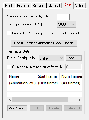
Slow Down Animation by a Factor of #
This integer value allows the output animation keyframe data to be slowed down in time. This is accomplished by multiplying the keyframe time values by the specified integral value. Thus, a value of 2 will slow down the animation by a factor of 2. The default is 1.Ticks Per Second
This combo box determines how many "ticks per second" the output animation will be scaled by.DirectX keys are output by multiplying the frame time by (ticks-per-second / frames-per-second). The ticks-per-second is set by this combo box, and the frames-per-second is set by the current scene being exported. Most DirectX viewers use 3600 as the "ticks per scond", but it has been reported that some newer DirectX viewers have opted for the more sane 4800 ticks per second.
Fix up -180/180 degree flips from Euler key lists (Maintain Euler Curve Continuity)
This option fixes Euler rotation channels which flip back and forth between values close to 180 degrees and -180.0 degrees, from key to key, before they are exported to DirectX as quaternion rotation channels.. Normally this flipping will not pose a problem unless DirectX "slows down" an animation for previewing in slow motion, and does sub-key interpolation (in such cases the objects may appear to randomly spin in the wrong direction at specific keys).Background Info:
Euler animation data (3 explicit X, Y and Z rotation channels) needs to be "resampled" from one mathematical format to another, Euler notation to quaternion notation, for DirectX export.The resampling process first converts the Euler rotation value(s) at each keyframe to a 4x4 rotation matrix, and then the matrix is decomposed into explicit (X, Y, Z) Euler rotation angles, of the desired Euler order. The Euler angles will always be in the range -180 to 180 degrees.
The primary disadvantage of the traditional Euler decomposition method comes about when DirectX attempts to view the animation in a "slow motion" mode. Since two adjacent frames might have values of, say, -179.9 and 179.9 (or vice versa) on one of the Euler angles, the sub-frame interpolation between these values will result in a quick spin through 359.8(!) degrees, rather than the intended 0.2 degree change. When a "slow motion" mode is not in effect, the user will traditionally never see the sub-frame interpolated values because the -179.9 and 179.9 rotations are absolute and correct values (needing no further interpolation between them).
Problem example: if the exported Euler source rotations are 150.0 deg, 179.0, deg, 185.0 deg, 190.0 deg then after resampling the rotations will be 150.0 deg, 179.0 def, -175.0 deg, -170.0 deg. These are correct. However, file formats such as DirectX, during slow-motion playback where sub-frame interpolation is performed, will look at the 179.0 to -175.0 degree interval and create new interpolated values through a 354 degree rotation interval and not the shorter 6 degree rotation.
What This Option Does:
Enabling this option will allow an additional algorithm to be used which detects cases of "-180/180 degree Euler Flips" and attempts to fix them. This alternative algorithm will take the previous frame of animation into account when performing rotation resampling. It will attempt to decompose the rotation into a equivalent set of Euler angles which represents the smallest Euler-space change of values. This makes the algorithm very good for preventing -180/180 discontinuities in the Euler animation curves. This allows "slow motion" sub-frame interpolation to function as ideally expected.One possible down-side to this alternative algorithm is that Euler angles are free to "drift" away from the normal -180/180 range. Let us suppose you have an animation of a spinning top. Under the traditional algorithm, the top might spin from 0 to 180, then a discontinuity effect occurs, causing the next frames to go from -180 to 0 to 180, and so forth. With this option enabled, the top would spin from 0 to 180, then from 180 to 360 to 540, and so forth. There are hypothetical scenarios where users might not want that to happen. If that is the case, disable this option to ensure that all angles are clamped to the -180/180 range.
Modify Common Animation Export Options
Pressing this button will display the 'Common Animation Export Options' dialog box. This dialog box controls how internal animation data is optionally re-sampled during its export to a DirectX file. These export options are most important for properly exporting animation data to DirectX.Animation Sets
In 3D game design it is often useful to have a series of reuseable animation 'clips' for common character cycles, such as an animation clip for walking, jumping, running, etc. In DirectX these are called 'animation sets'.Unfortunately most common 3D animation systems, such as 3ds Max, Maya and LightWave use a single timeline for a character's entire animation. Hence, game developers will concatenate all the animation cycles (walk, jump, run) into a single continunous animation timeline of keyframes.
This list view on the Okino DirectX exporter allows this single timeline of animation to be segemented into discreet animation sets (clips) before going out to DirectX. The default is to output all animation associated with each mesh as 'AnimationSet0'. Any number of animation sets can be defined, each with their own start and end frames.
NOTE: in order to break apart the single Okino timeline into multiple animation sets for DirectX the Okino "resampler" must be enabled implicitly. Thus, the dialog boxes which allow you to enable/disable animation resampling and the choice of "Resample to keyframe list extents vs. entire animation extents" will be ignored.
Offset Animation Sets To Start at Frame # XXX
This option allows each exported animation set to always start at a specified frame number in the exported DirectX file. By default, when this option is disabled, each animation set is output starting at the frame number at which the animation set is defined (such as frame 50). When this option is enabled, all animation sets are shifted in time so that they always start at the specified frame number (such as 0). This option is useful if your destination game engine wishes to see each animation segment start at a fixed frame number.Add New...
Press this button to add a new animation set to the current configuration. The dialog box will allow the animation set name to be changed, as well as the start/end frame numbers (or, if you prefer, the start frame number and number of frames). Note: the animationset name you enter will automatically be made unique. The current start and end frame numbers will be derived from the extents of the current animation defined inside the Okino scene graph.
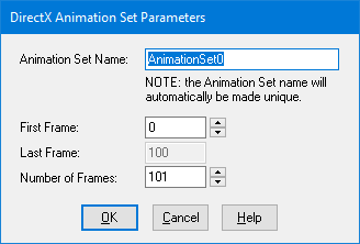
The "Default" configuration cannot be modified (it will always contain the full animation extents). Before pressing the "Add New.." button make sure you have chosen a configuration from the drop-down combo box which is not the "Default". You can press the "Modify" button to add a new configuration first.
Edit...
Highlight an existing animation set on the listview and press this button to edit it. If you change the name of the animation set, and that name already exists, then the new name you have entered will be made unique. NOTE: the "Default" configuration cannot be edited (it will always contain the full animation extents).Delete
Highlight an existing animation set on the listview and press this button to delete it.Delete All
Press this button to delete all animation sets defined within the current configuration. The exporter will go back to its default mode of exporting all keyframes to 'AnimationSet0'.Preset Configuration Combo Box and 'Modify'
Game developers will often work with multiple 3D scene files for their projects. Each will require its own set of animation sets and related start/end frame ranges. A 'Preset Conguration' allows such game developers to group together animation sets into different named configurations. Hence, you may have a configuration named 'Opening sequence' for the game with 4 animation sets and another called 'Warrior sequence' with 5 animation sets.Since you may wish to archive these configurations and related animation sets along with your game asset data, the data is stored in the following directory on your machine:
\documents and settings\<your login name>\application data\okinoand named
okino_directx_exporter_animationset_configurations.datThe DirectX exporter will only use the animation sets which are currently used by the configuration shown in the 'Preset Configuration' combo box.
To create a new configuration, or delete one or all existing configurations (as well as the animation sets associated with them), press the 'Modify...' button. This will cause the following dialog box to appear:
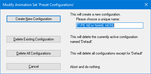
Create New Configuration
Press this button to add a new configuration. You must enter a unique name in the 'TYPE NEW NAME HERE' edit box first. All keys will be exported for the new configuration until you do a 'Add New...' to define sub-ranges for each associated animation set.Delete Existing Configuration
Press this button to delete the currently active configuration. You cannot delete the 'Default' configuration.Delete All Configurations
Press this button to delete all existing configurations, except for the 'Default' one.
- If the 'Encapsulate Mesh Data' option is enabled then the .X file created with this export converter should be loaded using the 'Frame::Load' command.
- If the 'Encapsulate Mesh Data' option is disabled then the .X file created with this export converter should be loaded using the 'Mesh::Load' command.
- If the .X file contains animation data then it should be loaded with the 'AnimationSet::Load' command.


