| You are here: Home » Import CAD Formats » NGRAIN's 3KO Solutions |
|
See Also:
- IGES import solutions page.
- STEP import solutions page.
- Parasolid import solutions page.
- Autodesk Inventor import solutions page.
- ProE/Creo (Elements/Pro, Elements/Modeling, ProductView) import solutions page.
- SOLIDWORKS import solutions page.
As a complement to Okino's full featured IGES import converter, this IGES export converter allows trimmed NURBS, NURBS curves, 3d pointsets (point clouds) and linear lineset data to be exported in various flavors of the IGES file format. This export converter is useful for transferring data to CAD/CAM packages which will most likely read in an IGES file.
In general most CAD programs which accept IGES files require that the geometry data be "trimmed NURBS" or "BREP solids". This IGES exporter will only output "trimmed NURBS" (in IGES entities 144/142/128) when the source data is also "trimmed NURBS", such as from Maya (and only when the geometry data was modeled as NURBS and not polygons).
This IGES exporter can also output all 3D geometry items as pure polygons meshes, as IGES entity # 106 (copious data). However, as outlined in the next paragraph, this option tends to confuse users of this IGES exporter since they expect such #106 data to be read into all CAD modelers. In general there are very few CAD programs which will import and accept #106 copious data polygon meshes because they only accept NURBS and not meshes. This option to output #106 copious data was added for one customer who wanted to output a text font outline to ProE/Creo, after which the data was imported as a 2D drafting outline, traced, and turned into a 3D model using interactive ProE/Creo drawing tools.
Important Notice: This export converter CANNOT convert polygon mesh data to an IGES file as NURBS or solids. It is a very common request that Okino customers will want to take polygon mesh data from programs such as 3ds Max, Maya, Cinema-4D, SketchUp, etc. into solids modeling programs such as ProE/Creo, SolidWorks, Solid Edge, Autodesk Inventor, etc. This is just not possible, even if you don't believe it. Solids modelers require that the IGES file only contains trimmed NURBS data, usually with additional BREP stitching data to make the trimmed NURBS into "solids". Polygon mesh data cannot be converted back to trimmed NURBS or solids simply by exporting to IGES; to do that you will need to purchase a "surface reconstruction" program which allows you to interactively reconstruct a NURBS model out of a mesh model, and only then will you be able to export a newly reconstructed NURBS surface to an IGES file. We can refer you to several companies which sell surface reconstruction software: Geomagic Design, Geometry Systems - GSI Studio and headus, CySlice v3. Okino has no affiliation with any of these companies. This list is from openly available and published information.
In the end, due to these high prices, most people just rebuild their mesh models in a good and very popular MCAD modeller like SolidWorks as it costs less than a mesh reconstruction program (the pro of SolidWorks also includes an interactive mesh reconstuction module). As one last note we always mention to our users, some MCAD modellers allow a mesh model to be imported as a "proxy graphic" that can be used as a reference to hand-build a new NURBS model over top of it - such proxy graphics cannot be edited or used in any solids modelling operations.Note: most 3D printers can accept VRML2 and STL formats, which are not "CAD formats". CNC milling machines, however, require the tangential information from a true NURBS surface and hence many of them will only accept a proper NURBS-based file format.
This dialog box contains several miscellaneous IGES export options:
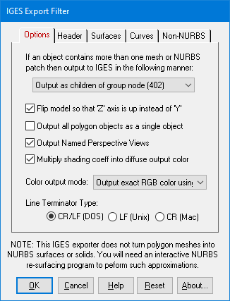
'Solid Assembly' Output Method
This option determines how multiple NURBS surface patches inside a single Okino object definition will be output to the IGES file.This option also controls whether data exported as meshes (#106 copious data) will be grouped together in a single #402 or #184 parent entity.
Output as Separate NURBS Patches (128)
Each NURBS patch will be output as a separate and non-grouped IGES NURBS patch entity (#128). For example, if inside Okino software you had a single object that looked like an airplane body (but which was composed of 100 NURBS patches), then this option would simply output 100 NURBS patches to the IGES file.Output as Children of a Group Node (402)
This option outputs the 100 NURBS patches (of our airplane example) as 100 separate NURBS patch entities (#128) in the IGES file, but all the patches will be grouped under a single group node (#402) which has the same name as the object definition in Okino software. This is the default.This option also allows polygon mesh data (exported as #106 copious data) to have all of the #106 entities grouped together under a single #402 grouping node, with the grouping node named the same as the internal Okino instance name.
Output as 'Solid Assembly' (184)
This option outputs the 100 NURBS patches (of our airplane example) as 100 separate NURBS patch entities (#128) in the IGES file, but all the patches will be grouped under a 'Solid Assembly' node (#184) which has the same name as the object definition in Okino software. While the resulting data will not form a true 'B-Rep' solid representation, it may come in useful for some CAD programs which can accept the 'Solid Assembly' (184) entity.This option also allows polygon mesh data (exported as #106 copious data) to have all of the #106 entities grouped together under a single #184 assembly node, with the assembly node named the same as the internal Okino instance name.
Flip model so that 'Z' axis is up instead of 'Y'
Many CAD modeling programs use a "Z" up coordinate system, whereby Okino software (and others) use a "Y" up coordinate system. This checkbox is enabled by default so that the Y-up data of the internal database will be exported in the re-oriented Z-Up coordinate system for the IGES file.Output all polygon objects as a single object
If this checkbox is enabled (checkmarked) then all NURBS objects and mesh objects will be combined together and output as a single mesh object to the IGES file (#160 copious data). This option does not affect NURBS curves, line sets or 3D point sets.Output Named Perspective Views
If this checkbox is enabled (checkmarked) then a #410 perspective camera entity will be output to the IGES file.Multiply shading coeff into diffuse output color
If this checkbox is enabled (checkmarked) then the diffuse shading coefficient of an internal material (surface definition) will be multiplied into the diffuse material color before being output to the IGES file -- doing so will be mathematically more precise for the exported color, but may make it too dark for some CAD packages. Disabling this option will output the raw surface color of the material, and thus will make the final color brighter in the destination progam.Color output mode:
This combo box determines how color information will be output to the IGES file.Always use IGES color # 0 (IGES default)
No color info is output. Each entity will be assigned color # 0 which means "undefined".Map RGB color to 1 of 8 IGES colors (inexact)
The 24-bit RGB color will be mapped to 1 of 8 default IGES colors.Output exact RGB color using entity # 314
The exact 24-bit RGB color will be output to the IGES file and associated with each entity using #314. This is the best way to associate color info with each geometric entity in the IGES file. The 24-bit RGB color will be scaled to the range of 0..100 for each intensity component.
The "Header" dialog box contains user-settable options that will be embedded within the "Global Header" section of the IGES file. You are free to set these options to whatever you desire.
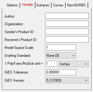
Author
This is an optional author name string.Organization
This is an optional company or organization string.Sender's Product ID
This is an optional string to identify the product by the sender of the IGES file.Receiver's Product ID
This is an optional string to identify the product for the receiver of the IGES file.Model Space Scale
This floating point value will be written to the "Model Space Scale" parameters in the Global header section of the IGES file. It contains the "ratio of the model space to real-world space (e.g.: 0.125 indicates that 1 model space units equals 8 real-world units). The default is 1.0.Drafting Standard
This drop-down box lists the various drafting standards that the exported IGES file is to conform to:
- None (0) - No standard specified (default)
- ISO (1) - International Organization for Standardization
- AFNOR (2) - French Association for Standardization
- ANSI (3) - American National Standards Institute
- BSI (4) - British Standards Institute
- CSA (5) - Canadian Standards Association
- DIN (6) - German Institute for Standardization
- JIS (7) - Japanese Institute for Standardization
IGES Tolerance
This is the tolerance to which the exported IGES file conforms to. For example, if set to 0.0001 then all points in space which are closer together than 0.0001 units will be considered equal. You may find that you have to set this tolerance value higher (in steps of 10x) for the destination CAD/CAM program to properly read in the IGES file. In most cases you can keep this value at the default number (1e-6) because the NURBS geometry being exported should be of high quality and high tolerance.IGES Version
This defines the IGES version to which the exported file conforms to. The default is v5.2 (1993) but the exported file is generic enough to use literally any of these IGES versions.
The IGES export converter has the ability to export both trimmed NURBS data and raw polygon data. This dialog box controls the output of the NURBS data.
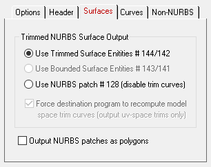
Trimmed NURBS Surface Output
When NURBS data is output to an IGES file is it commonly output as an un-trimmed NURBS patch (entity # 128) and a parent entity that associates one of more trim curves with the raw NURBS patch (#144). The following radio buttons control how these trimmed NURBS will be output to the IGES file:Use Trimmed Surface Entities # 144/142
The trimmed NURBS will be output using a parent trim entity (#144), one or more trim curves entities (#142) and the raw NURBS patch geometry entities (#128). This is the most modern and common method used to transfer trimmed NURBS via IGES files.Use NURBS patch # 128 (disable trim curves)
No trimming information will be output to the IGES file. Only the raw, un-trimmed NURBS patches (#128) will be output.Output NURBS Patches as Polygons
If this checkbox is enabled then all NURBS and trimmed NURBS patches will be converted to triangles before being exported to the IGES file. The method by which the polygons are stored in the IGES file will be controlled by the options shown on the "Polygons" dialog panel.
This panel controls the output of 3D NURBS curves and 3D spline shapes. The 3D NURBS curves are in no way related to the 2D trim curves of a NURBS surface.
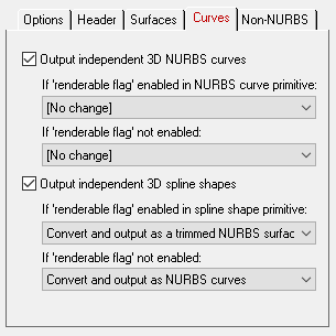
Output independent 3D NURBS curves
The NuGraf/PolyTrans 3D database has a very extensive NURBS curve sub-system. Each NURBS curve object can have 1 or more NURBS curves associated with it. Multiple curves inside a single object can either be considered to form a single continuous "composite" curve, or each curve can be considered unique, closed, planar (in world space) and oriented such that the curves of the object can be directly converted into a trimmed NURBS surface (in other words, the first curve forms the boundary of the surface and subsequent closed curves form the holes).The following options control how the various NURBS curve configurations can be converted during the export phase. An extensive internal NURBS curve conversion and cross-conversion system exists.
If 'renderable flag' enabled in NURBS curve primitive:
If the 'renderable' flag of a NURBS curve primitive is internally enabled, and the curve(s) form closed loops, then it is possible to convert the NURBS Curve primitive into a 3D format that is renderable: either a mesh, a trimmed NURBS surface or a Spline Shape. The following options define what will be done to NURBS Curves primitives during the export phase when their 'renderable' flag is enabled:[No Change]
No change. The NURBS Curve primitive will be exported as-is.Convert and Output as Polygon Mesh
The NURBS Curve primitive will be converted into a mesh object prior to export.Convert and Output as Trimmed NURBS Surface
The NURBS Curve primitive will be converted into a corresponding trimmed NURBS surface (patch). If the conversion process cannot be made then it will be output as a polygon mesh instead.If 'renderable flag' not enabled:
If the 'renderable' flag of a NURBS Curve primitive is not enabled then the curves will be considered just as plain curves that cannot be seen when rendered. In this case, the following options define what will be done to NURBS Curves primitives during the export phase when their 'renderable' flag is disabled:[No Change]
No change. The NURBS Curve primitive will be exported as-is.Output Composite NURBS Curve as a Single Curve
No change except in the case when the NURBS curve primitive is defined as a single composite curve made up of multiple curve segments. In this case the multiple curve segments will be temporarily converted to a single NURBS curve before export.Output independent 3D spline shapes
The NuGraf/PolyTrans 3D database has a very extensive spline primitive sub-system. This primitive accommodates one or more spline curves per primitive. If the multiple spline curves are each closed then the overall Spline Shape is termed "renderable" and can be thus converted into a polygon mesh or a corresponding trimmed NURBS surface (patch). For example, the letter "B" can be defined by 3 Bezier curves, the first forming the outer boundary and the latter two forming holes. Note, that unlike the NURBS Curve primitive, each spline curve of the Spline Shape is composed of only a single curve segment (no composite spline curves are allowed).The following options control how the various Spline Shape configurations can be converted during the export phase. An extensive internal Spline Shape conversion and cross-conversion system exists. The Spline Shape primitive also handles almost every major spline type (Bezier Spline, B-Spline, Cardinal Spline, Linear Spline, Tensioned Spline, TCB Spline), and their internal cross conversion (between spline types) or between the various spline types and a NURBS curve.
If 'renderable flag' enabled in spline shape primitive:
If 'renderable flag' not enabled:Convert and Output as Polygon Mesh
The Spline Shape primitive will be converted into a mesh object prior to export.Convert and Output as Trimmed NURBS Surface
The Spline Shape primitive will be converted into a corresponding trimmed NURBS surface (patch). If the conversion process cannot be made then it will be output as a polygon mesh instead.Convert and Output as a NURBS Curve Object
Each spline curve of the Spline Shape primitive is resampled into a corresponding NURBS Curve segment and placed into a single NURBS Curve primitive. The 'renderable' flag of the new NURBS Curve primitive will be disabled. The final NURBS Curve primitive will look similar (within an error tolerance) to the original Spline Shape.
"Non-NURBs" Dialog Box Options:
This panel controls the output of non-NURBS primitive data, such as meshes, lines and points.
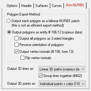
Polygon Export Method
The following two radio buttons choose the method by which the polygons will be stored within the IGES file:Output Each Polygon As a Bilinear NURBS Patch
Each and every polygon will be converted to an un-trimmed bilinear NURBS patch. This is extremely in-efficient but there are some CAD/CAM programs which can only read NURBS data (and not polygons), hence this is the only method available to get polygon data into these programs.Output Polygons as Entity # 106:12 (copious data)
Polygon meshes will be output to the IGES file using 'copious data' entity # 106, form # 12. This is the default method. Not all programs which read in IGES will be able to accept and display copious data (many CAD/CAM programs can only deal with NURBS data, not polygons).Output all polygons as 3-sided triangles
If this checkbox is enabled then all polygon data will be triangulated first prior to export.Reverse orientation of polygons
If this checkbox is enabled then the orientation of all the polygon vertices will be reversed. You may have to enable this option if the exported model appears 'inside-out' within the destination program.Output vertex normals (#106, form 13)
If this checkbox is enabled then vertex normals (if available) will be stored along with the raw vertex coordinate data. This option is enabled by default. This vertex normal information is useful for programs which require such data to make a rendered object appear smooth.Flip vertex normals
If this checkbox is enabled then the vertex normals output to the IGES file will be 'flipped' so that they point in the opposite direction.Output 3D lines as:
This combo box determines how line segments are output to the IGES file. Internally, lines are "polylines" in which each polyline can handle 2 or more vertices, and each object definition can have one or more polylines. IGES allows for various ways of handling line segments and polylines:{Don't output lines}
No lines will be output to the IGES file.2-point line elements (110)
All lines and polylines will be exploded into individual #110 line entities, each with 2 vertices each. This tends to be very inefficient for file size yet may be the most commonly recognized IGES entity type for taking line segments to other programs.Linear 3D paths (copious data # 106:12)
All lines and polylines will be output to the IGES file as "copious data" linear 3D paths. This seems to be a little known or little used aspect of the IGES file format but it is one of the more efficient methods to embed line data in IGES files. Each polyline will be output as an N-vertex linear 3D path and not exploded into individual 2-point vertex lines as used by the #110 line entity.Linear BSpline curves (126)
All lines and polylines will be output to the IGES file as linear Bspline curves. This is not the most efficient method to export line data to IGES files but it may be the only method available to accept such linear data in a downstream CAD application.Group lines together (#402)
If this checkbox is enabled then all #110, #106 or #126 line entities output to the IGES file will first be made children of a #402 grouping entity in the IGES file. The grouping will be made according to the objects inside the Okino database. For example, if there is an indexed lineset with 1000 lines in it (named "linetest"), then the IGES file will contain one #402 with a name of "linetest", and 1000 110/106/126 entities parented to this grouping node.Output 3D points as:
This combo box determines how 3D pointsets ("point clouds") are output to the IGES file.{Don't output points}
No 3D points will be output to the IGES file.Point array (copious 106:2). No point color.
All points will be output to the IGES file as "copious data" 3D points. All points of the 3D pointset will be output to the same #106:2 entity. Not all downstream 3D CAD packages will recognize points in this type of primitive. No vertex color info can transfer using this primitive.Individual points + color (116).
For each 3D point in a pointset, a single #116 "point" entity will be output to the IGES file, along with an optional vertex color (scaled into the 0..100 range).Individual points + color (116). Group under # 402.
This is the same as the previous option except that all of the #116 entities belonging to the same internal 3D pointset will be grouped together in the IGES file using a #402 grouping node. This is the preferred option to choose. If your internal dataset has 4 distinct pointset objects, then this #402 grouping method will allow the exported points to remain distrinct from each other.

